Search Result
25 expansions found
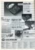
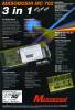
Manufacturer Mainhattan Data, Germany | Date 1992 | Amiga A2000, A3000, A4000 | Interface Zorro II | Autoconfig ID 2159 / 1 |
- IDE controller
- autobootROM - autobooting requires at least Kickstart 1.3
- RDB compatible
- 40 pin internal IDE header
- autoboot disable jumper
- available as filecard or slotcard
- filecard: full length card with place for a 3.5" hard disk on the card
- slotcard: half length card, no place for mounting a hard disk

front side

back side
- A-Team1.dms
install disk v1.0
692 kB - A-Team2.dms
install disk v2.1 (25.5.1992)
668 kB
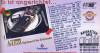
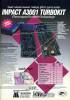
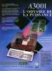
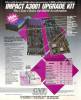
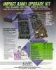
Advert (DE)
1992-10
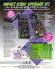
Manufacturer Great Valley Products, USA | Date 1989 | Amiga A2000 | Interface CPU slot | Autoconfig ID 2017 / 8,9,13 |
- processor
- 68030 @ 16 / 25 / 28 / 33 / 50 MHz, PGA
- optional 68882 @ 16 - 50 MHz, PGA - can be clocked at different speed than the CPU
- optional memory daughterboards
- 68030-RAM8:
- eight 30 pin SIMM sockets accept 4 or 8 MB RAM
- supports only special 1 MB Nibble Mode SIMMs, they are more expensive than GVP SIMMs
- accepts SIMMs in groups of four
- 68030-RAM32: (from 1991)
- eight 64 pin SIMM sockets accept up to 8 or 20 MB RAM
- supports only special 1 or 4 MB, 60 ns GVP SIMMs
- 60 ns SIMMs are required for 50 MHz, 70 ns for 33 MHz, 80 ns for 25 MHz
- 16 - 33 MHz boards support 1 MB SIMMs only, possible configurations are 2, 4 and 8 MB
- 50 MHz boards support 4 MB SIMMs, possible configurations are 4, 8, 12, 16 and 20 MB
- using a 4 MB SIMM requires four 1 MB SIMMs to be installed in sockets 3 to 6, so the 4 MB SIMMs can only be installed into sockets 7 to 10
- optional IDE controller
- two autoboot ROM sockets
- to activate the IDE controller only the boot EPROM(s) (gvpat.device) has to be installed on the main board - the first version of the driver software required two EPROMs, later ones required only one
- does not support drives that has more than 1024 cylinders
- controller uses byte-swapped storaging, so the HDD will be unreadable on other controllers without that feature
- 40 pin internal IDE header
- A-Max II driver (gvpat.amhd) - requires gvpat.device v2.4 and A-Max v2.06
- notes
- autobooting requires at least Kickstart 1.3 - the autoboot ROM should not be installed with Kickstart 1.2
- two ROM sockets for UNIX boot ROMs that require an A2090A SCSI controller - these ROMs are compatible with those on the A2630
- 68000 fallback mode selectable by jumper
- the memory and IDE controller is also deactivated in fallback mode
- jumper settings - A3001
| Jumper | Default | Description |
|---|---|---|
| J4 | OPEN | Install to clock FPU from oscillator U2 |
| J5 | SHORTED | Remove to disconnect FPU from oscillator U1 |
| J6 | OPEN | Install to disable the 68030s caches |
| J7 | OPEN | Install to disable the 68030s MMU |
| J8 | OPEN | Install to enable Unix boot register |
| J9 | SHORTED | Remove to enable 68030 boot EPROMs |
| J10 | SHORTED | Remove for use in German 4-layer A2000s |
| J11 | OPEN | Install to boot in 68000 mode |
| J12 | OPEN | Reserved |
| J13 | OPEN | Reserved |
| J14 | SHORTED | Reserved |
| J15 | OPEN | Reserved (AT interface) |
| J16 | SHORTED | Reserved (AT interface) |
- jumper settings - RAM8 board
| Jumper | Default | Description |
|---|---|---|
| J1 | OPEN | Reserved |
| J2 | OPEN | Reserved |
| J3 | SHORTED | Reserved |
| J4 | SHORTED | Reserved |
| J5 | SHORTED | Remove to enable full 8MB of 32-bit RAM |
| J6 | SHORTED | Reserved |
| J7 | OPEN | Reserved |
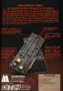
 - Series I front side")
Series I, front side
 - Series I with RAM8 board back side")
Series I with RAM8 board, back side
 - Series I front side")
Series I, front side
 - Series I with RAM8 board back side")
Series I with RAM8 board, back side
- A3001.dms
install disk (01.11.89)
320 kB - amiga.html#gvp
Ralph Babel
UNIX boot ROM image
1 kB - amiga.html#gvp
Ralph Babel
IDE ROM image
gvpat.device v4.1
10 kB
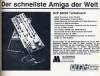
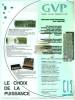
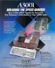
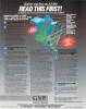
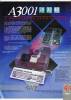
Advert (DE)
1989-10
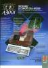
Advert (DE)
1990-01
Advert (DE)
1990-05
Advert (DE)
1990-06
Advert (US)
1989-06
Advert (FR)
1989-09
Advert (US)
1989-09
Advert (FR)
1989-12
Advert (US)
1989-12
Advert (US)
1990-01
Advert (US)
1990-03
Advert (US)
1990-04
Advert (FR)
1990-05
Advert (FR)
1990-06
Advert (US)
1990-07
Advert (US)
1990-08
Advert (FR)
1990-09
Advert (FR)
1990-11
Advert (US)
1990-12
Advert (US)
1991-04
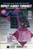
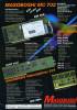
Manufacturer Great Valley Products, USA | Date 1991 | Amiga A2000 | Interface CPU slot | Autoconfig ID 2017 / 8,9,13 |
- processor
- 68030 @ 33 / 50 MHz, PGA
- 68882 @ 33 / 50 MHz, PGA - clocked separately from the CPU
- memory daughterboard (68030-RAM32)
- eight 64 pin SIMM sockets accept up to 8 or 20 MB RAM
- supports only special 1 or 4 MB, 60 ns GVP SIMMs
- 60 ns SIMMs are required for 50 MHz, 70 ns for 33 MHz, 80 ns for 25 MHz
- 16 - 33 MHz boards support 1 MB SIMMs only, possible configurations are 2, 4 and 8 MB
- 50 MHz boards support 4 MB SIMMs, possible configurations are 4, 8, 12, 16 and 20 MB
- using a 4 MB SIMM requires four 1 MB SIMMs to be installed in sockets 3 to 6, so the 4 MB SIMMs can only be installed into sockets 7 to 10
- IDE controller
- autoboot ROM (gvpat.device)
- does not support drives that has more than 1024 cylinders
- autobooting requires at least Kickstart 1.3 - the autoboot ROM should be removed with Kickstart 1.2
- controller uses byte-swapped storaging, so the HDD will be unreadable on other controllers without that feature
- 40 pin internal IDE header
- A-Max II driver (gvpat.amhd) - requires gvpat.device v2.4 and A-Max v2.06
- jumper settings
- main board (rev 7):
J4
ON
OFFJ5
OFF
ON- FPU clock
- from oscillator U2
- from oscillator U1J10
ON
OFFJ12
ON
OFFJ13
ON
OFFJ14
OFF
ON- clocking mode
- A2000-A german motherboard, 68000 must be removed
- A2000-B motherboardJ6 - MMU: ON - disable J7 - CPU clock: OFF - 50 MHz, ON - lower J9 - 68030 Boot code EPROMS (U23 and U25): OFF - enable J11 - 68000 fallback mode: ON - enable J15 - IDE autoboot EPROM (U34): ON - enable J17 - IDE autoboot EPROM type: ON - 27256, OFF - 27128 J18 - IDE drive: OFF - connected (with autoboot EPROM v3 or later) J1, J16
ONJ2
OFF
- reserved - memory board (rev 3):
J3
OFF
ONCN11
OFF
2-3CN13
ON
OFF
- 50 MHz
- lower clockJ5
ON
OFF- memory address of CN7-CN10 SIMMs
- Zorro II address space (with 1 MB SIMMs only)
- 0x01000000 (with 4 MB SIMMs only)J1, J4, J6, J8
ONJ2, J11
OFFCN12
1-2
- reserved
- notes
- two ROM sockets for UNIX boot ROMs that require an A2090A SCSI controller - these ROMs are compatible with those on the A2630
- the memory and IDE controller is also deactivated in 68000 fallback mode
 - Series II front side")
Series II, front side
 - Series II back side")
Series II, back side
 - RAM32 board front side")
RAM32 board, front side
 - RAM32 board back side")
RAM32 board, back side
- amiga.html#gvp
Ralph Babel
UNIX boot ROM image
1 kB - amiga.html#gvp
Ralph Babel
IDE ROM image
gvpat.device v4.1
10 kB
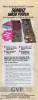
Advert (US)
1991-05
Manufacturer Breitfeld Computersysteme, Germany | Date 1993 | Amiga A2000, A3000, A4000 | Interface Zorro II | Autoconfig ID 2126 / 1 |
- IDE controller
- autobootROM - autobooting requires at least Kickstart 1.3
- RDB compatible
- two 40 pin internal IDE headers
- can handle up to four hard disks
- half length card - no place for mounting a hard disk
- disable switch
- versions with ROM 626 or above have read/write problems with files larger than 130 kB

front side

back side

front side

back side
- AccessX-20.dms
install disk v2.0
483 kB
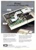
Manufacturer ICD, USA | Date 1990 | Amiga A500, A1000, A2000, CDTV | Interface 68000 socket | Autoconfig ID 2071 / 2 |
- IDE Controller
- small 1" by 3" board that connects to the 68000's socket
- fits in the CDTV if a shallow IDE connector is used
- AdIDE 44 (Novia) for 2.5" internal drives
- covers the Paula and CIA A chips
- mounting brackets and screws are supplied for mounting the hard disk inside an A500
- AdIDE 40 (Prima) for 3.5" drives
- drives can be fitted into an A500 in place of the built-in floppy drive using the Shuffle Board
- autobooting (adide.device or icdide.device) - requires at least Kickstart 1.3
- autobooting is problematic with the CDTV - either a boot floppy has to be used (which a bare CDTV lacks), or after a reset by selecting the hard disk in the Early Startup Menu (which require at least Kickstart 2.0)
- incompatible with Western Digital and IBM hard disks
- AdIDE 44 rules out accelerators that connect to the 68000's socket due to mechanical constraints
- AdIDE 40 is compatible with processor expansions if the AdIDE is fitted below the accelerator - reported to be functional in A500 are CSA Derringer and Mega-Midget Racer, as well as Microbotics VXL*30
- older software revisions work only with 68000 processor cards
- A-Max II driver (icddiskide.amhd)
 & 44 (Novia) - front side")
front side
 & 44 (Novia) - back side")
back side
- AdIDE2.pdf
installation manual
68 kB
- ICDPrepHD-40.dms
install disk v4.0
ICDPrepHD v4.0, adide.device v4.0r1, adscsi.device v4.0r1, icddisk.device v3.5r1, trifecta.device v4.0r1
117 kB - ICDPrepHD-42.dms
install disk v4.2
ICDPrepHD v4.2, adide.device v4.0r1, adscsi.device v4.0r1, icddisk.device v3.5r1, trifecta.device v4.0r1
117 kB - ICD-AdIDE.dms
Installer's Heaven
install disk
284 kB
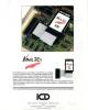
Advert (US)
1991-04
Advert (US)
1991-07
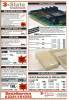
Manufacturer 3-State, Germany | Date 1992 | Amiga A2000, A3000, A4000 | Interface Zorro II | Autoconfig ID 8738 / 0,34 |
- SCSI 2 and IDE controller
- uses polled I/O instead of DMA transfer
- autoboot ROM (SCSI-Apollo.device) - autobooting requires at least Kickstart 1.3
- support for Rigid Disk Block
- Direct SCSI is supported only on the SCSI part of the controller
- place for a 3.5" hard disk on the card
- internal 50 pin SCSI header and 40 pin IDE header
- external DB25 SCSI connector
- hard disk activity LED
- disable switch
- memory
- sixteen ZIP sockets accept 8 MB RAM
- supports 1M×4 FastPage or Static Column ZIPs
- accepts ZIPs in groups of four giving 2, 4, 6 or 8 MB RAM
- two 30 pin SIP sockets accept 2 MB RAM
- the SIP sockets are hardwired to the first bank of ZIP sockets, they cannot be used at the same time

front side

back side
- Apollo2000.pdf
User Manual
4.3 MB
- ApolloInstall-50.dms
install disk v5.0
197 kB - apollo.2030hdinstall.DMS
Installer's Heaven
install disk
197 kB
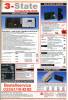
Advert (DE)
1992-08
Advert (DE)
1993-01
Manufacturer 3-State, Germany | Date 1992 | Amiga A2000, A3000, A4000 | Interface Zorro II | Autoconfig ID 8738 / 34 |
- IDE controller
- autoboot ROM (AT-Apollo.device) - autobooting requires at least Kickstart 1.3
- support for Rigid Disk Block
- place for a 3.5" hard disk on the card
- internal 40 pin IDE header
- hard disk power connector
- hard disk activity LED connector
- autoboot disable jumper
- A-Max II and Chamäleon drivers
- no option for memory expansion

front side

back side

front side

back side
- ApolloInstall-50.dms
install disk v5.0
197 kB
Advert (DE)
1993-01
Vapourware
Manufacturer Gigatron, Germany | Date 1991 | Amiga A2000 | Interface 68000 socket |
- No description available.
Do you own this expansion, or have information about it? Please let us know.
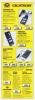
Advert (DE)
1990-11
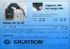
Manufacturer Gigatron, Germany | Date 1990 | Amiga A500, A1000, A2000 | Interface 68000 socket |
- IDE controller
- connects to the 68000's socket, the 68000 is replaced onto the board
- 44 pin header for 2.5" internal drives
- autoboot ROM, autobooting requires at least Kickstart 1.3
- autoboot can be disabled with a jumper, useful for Kickstart 1.2 and below
- mounting brackets and screws are supplied for mounting the HD inside an A500
- bundled with a 20 MB hard disk
- rules out accelerators that connect to the 68000's socket
- the board covers the Denise socket so it rules out many internal flicker-fixers

front side

back side
- Arriba-14.dms
install disk v1.4 (28.8.1991)
PrepArriba v1.1, LedArriba v1.1
350 kB
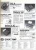
Advert (DE)
1990-07
Advert (DE)
1990-11
Advert (DE)
1991-08
Advert (DE)
1991-11
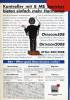
Manufacturer BSC / Alfa Data, Germany | Date 1992 | Amiga A2000, A3000, A4000 | Interface Zorro II | Autoconfig ID 2049 / 62092 / 6 |
- IDE controller
- the board is basically the combination of the A.L.F. IDE controller and the MemoryMaster memory expansion cards
- uses polled I/O, not DMA transfer
- RDB compatible
- 40 pin internal IDE header
- place for a 3.5" hard disk on the card
- delivered with A.L.F. 2 driver software
- during transfers the high and low bytes are swapped as the A600/A1200/A4000 and PCs do so the drives formatted with them can be handled by the AT-Bus 2008
- hard disk activity LED connector
- memory
- sixteen ZIP sockets accept 8 MB RAM
- supports either static column or page mode ZIPs
- accepts ZIPs in groups of four giving 2, 4, 6 or 8 MB configurations
- RAM and HD can be disabled separately by jumper

front side

back side

front side

back side
- BSC-HD.pdf
Controller Hardware and Software Installation Manual (english/german)
443 kB
- ATBus2008.dms
install disk
223 kB - AlfaPower_AT-Bus_ROM-610.zip
ROM v6.10
13 kB - oktapus.lha
Aminet
OktaPussy v2.1 (24.11.98)
106 kB

Advert (US)
1994-02
Advert (US)
1994-05
Advert (DE)
1991-11
Manufacturer Vortex, Germany | Date 1990 | Amiga A2000, A3000, A4000 | Interface Zorro II | Autoconfig ID 8215 / 3 |
- IDE controller
- 40 pin internal IDE connector
- autoboot ROM (vortex.device) - autoboots even under Kickstart 1.2
- not RDB compatible
- place for a 3.5" hard disk on the card
- memory
- four 30 pin SIMM sockets accept 2 or 4 MB RAM
- supports 1 MB SIMMs, 100 ns or faster

front side

back side
Advert (DE)
1990-05
Manufacturer Individual Computers, Germany | Date 1997 / 1998 | Amiga A2000, A3000, A4000 | Interface Zorro II | Autoconfig ID 4626 / 0 |
- IDE controller
- uses polled I/O, not DMA transfer
- two buffered IDE ports support up to four IDE devices
- each port is compatible with IDE splitters allowing up to a maximum of eight drives
- autoboot ROM
- two LED port activity connectors - one for drives 0 to 3, the other for drives 4 to 7
- software configurable IDE timing - even PIO mode 0 devices are compatible
- raw transfer speed is limited by the Zorro II bus to 3.58 MB/s
- supports hard disks larger than 4 GB
- can mount GVP or AT-Apollo formatted hard disks
- supported by Linux
- 26 pin local expansion slot for the optional HyperCom 3 Plus I/O module with two serial and one parallel ports
- Buddha Flash:
- 64 kB FlashROM
- clock port
- allows using expansions initially designed for the A1200 clock port (the Buddha Flash gold edition has golden clock port pins)
- when installed in Zorro slot, pin 40 of the card's clock port is towards the front side of the computer, pin 19 resp. pin 1 towards the rear side
- marked wire of clock port expansions go to pin 19 or pin 40, depending on the manufacturer's definition - e.g. expansions made by Individual Computers are installed with the red stripe on pin 40 (to the left), expansions of E3B mark pin 19 / pin 1 (to the right)

front side

back side

front side

back side

front side

back side
- bflash.lha
Individual Computers
Buddha Flash updater
74 kB - buddha.lha
Individual Computers
install disk
280 kB
Manufacturer Individual Computers, Germany | Date 2008 | Amiga A1000A500 A2000, A3000, A4000 | - - - | Interface side expansion port, side expansion port Zorro II | Autoconfig ID 4626 / 0 |
- IDE controller
- special edition of the Buddha Flash IDE controller that is intended to be used with the Phoenix A1000 motherboard, but can also be used with original A1000 as well as A500 and Zorro Amigas
- differences to Buddha Flash:
- smaller PCB
- hardware redesign, 5 chips instead of 8
- no 26 pin expansion slot
- floppy power connector
- the board can be installed in the following places:
- Front Slot Phoenix Board
- Side Expansion Port (Phoenix board, A1000 board, A500)
- Zorro Slot
- if the board shall be used at the A500, a special edition with a different mounted 86 pin connector is needed
- the board must not be installed in the front slot of the A1000 board
- when used at the Phoenix front slot, the INT6 signal has to be provided to the board as this signal is missing - the side expansion ports provide that signal, so the wire is not necessary when installed there
- height of the board was chosen so that a laptop CD drive (14mm) can be fitted above the card in the A1000
- when installed on the Phoenix board front slot, the L64 jumper has to be removed
- 2.5" hard disks can not be powered by the board due to thin PCB tracks - making them thick enough for that purpose would have been resulted in a more expensive multilayer board
- it is necessary to provide power to the board via floppy power connector
- in conjunction with a Phoenix X-Surf a new Mach chip is needed (includes also a fix which prevented the Amiga from booting with Kickstart v1.3)
- only one jumper on the board, next to the flash chip: open = flash write protected, closed = flashing possible
- small header in the middle of the board with two LED connectors
- clock port
- allows using expansions initially designed for the A1200 clock port
- when installed in Zorro slot, pin 40 of the card's clock port is towards the front side of the computer, pin 19 resp. pin 1 towards the rear side
- marked wire of clock port expansions go to pin 19 or pin 40, depending on the manufacturer's definition - e.g. expansions made by Individual Computers are installed with the red stripe on pin 40 (to the left), expansions of E3B mark pin 19 / pin 1 (to the right)
Manufacturer Individual Computers, Germany | Date 1997 | Amiga A2000, A3000, A4000 | Interface Zorro II | Autoconfig ID 4626 / 42 |
- combination of the Catweasel floppy controller and the Buddha IDE controller built into one device
- features all Buddha functions plus an additional IDE port for up to six IDE devices
- features all Catweasel functions plus a boot ROM which allows booting from floppy drives attached to it
- three 40 pin IDE headers
- 34 pin floppy header
- 26 pin local expansion slot for the optional HyperCom 3 Plus I/O module with two serial and one parallel ports
- not guaranteed to work with A1200 Zorro busboards - Winner Z4 board works properly, RMB boards fail
- supplied with the software packages of Buddha and Catweasel
- supported by Linux

front side

back side
- cwdisk0100.lha
Individual Computers
install disk
multidisk.device v3.48
361 kB - mdisk362.lha
Individual Computers
multidisk.device v3.62
22 kB
Manufacturer Individual Computers, Germany | Date 1998 | Amiga A2000, A3000, A4000 | Interface Zorro II | Autoconfig ID 4626 / 42 |
- combination of the Catweasel Mk2 floppy controller and the Buddha Flash IDE controller built into one device
- features all Buddha Flash and Catweasel Z-II Mk2 functions
- works with all A1200 Zorro busboards

front side

back side
- cwdisk0100.lha
Individual Computers
install disk
multidisk.device v3.48
361 kB - mdisk362.lha
Individual Computers
multidisk.device v3.62
22 kB
Manufacturer Individual Computers, Germany | Date 1997 | Amiga A2000, A3000, A4000 | Interface Zorro II | Autoconfig ID 4626 / 42 |
- combination of the Catweasel Mk2 floppy controller and the Buddha IDE controller built into one device
- uses the non-Zorro Catweasel Mk2 as a piggyback module
- features all Catweasel Z-II and Catweasel Mk2 functions
- each IDE port has its own activity LED connector

without Catweasel board, front side

front side

with Catweasel board installed, front side

Catweasel board, back side
- cwdisk0100.lha
Individual Computers
install disk
multidisk.device v3.48
361 kB - mdisk362.lha
Individual Computers
multidisk.device v3.62
22 kB
Manufacturer Mark Tomlinson, New Zealand | Date 1995 | Amiga A2000, A3000, A4000 | Interface Zorro II, ISA |
- allows using of inexpensive ISA cards on the Amiga
- does not support ISA DMA transfers (which is required for PC floppies)
- SANA-II drivers for NE1000 and NE2000 compatible ISA network cards are supplied
- supported by OpenBSD
- IDE controller
- autoboot ROM (xlide.device)
- supports the RDB standard, but filesystems are not loadable from the RDB
- can use an MFM / RLL 16 bit controller instead of the IDE interface
- serial interface
- two onboard serial ports (xlser.device)
- can be activated by plugging in one or two 8250, 16450 or 16550A UART chips
- DB25 and DB9 connectors
Manufacturer Expansion Systems, USA | Date 1991 | Amiga A2000, A3000, A4000 | Interface Zorro II |
- SCSI and/or IDE controller
- three versions, all share the same board with the necessary parts installed only
- DataFlyer 2000 SCSI (2000s):
- AMD 5380 SCSI controller
- 50 pin internal SCSI header
- optional external DB25 connector
- DataFlyer 2000 IDE (2000e):
- 40 pin internal IDE header
- DataFlyer 2000 SCSI+IDE has all the parts installed
- half length card with optional hard frame
- place for a 3.5" hard disk either on the back of the card or on the optional hard frame
- hard disk power connector
- hard disk activity LED connector, individual for SCSI and IDE
- expansion header for the optional DataFlyer RAM board
- autoboot ROM (ExpSys.device) - autobooting requires at least Kickstart 1.3, otherwise it has be disabled with a jumper
- autobooting can be also disabled by holding down the left mouse button during the boot sequence
- RDB compatible
- A-Max II driver (ExpSys.amhd)

IDE version, front side

IDE version, back side

SCSI version, front side

SCSI and IDE version, front side

SCSI and IDE version, front side
- DataFlyer-37e.dms
install disk v3.7E
387 kB - dataflyerScsiPlus.DMS
Installer's Heaven
install disk
390 kB
Manufacturer Kupke, Germany | Date 1994 | Amiga A2000, A3000, A4000 | Interface Zorro II | Autoconfig ID 2073 / 5 |
- Fast SCSI 2 and IDE controller
- FAS216 SCSI controller IC
- transfer speed is limited by the Zorro II interface
- 50 pin internal SCSI header
- 40 pin internal IDE header
- DB25 external SCSI connector
- RDB and SCSI Direct compatible
- autoboot ROM
- hard disk activity LED connector
- place for a 3.5" hard disk on the card
- disable switch at the back of the card
- IDE part can be separately disabled

front side

back side
Manufacturer Masoboshi, Germany | Date 1991 | Amiga A2000, A3000, A4000 | Interface Zorro II | Autoconfig ID 2157 / 38535 / 4 |
- SCSI 2 and IDE controller
- MasterCard 302
- IDE controller only
- 40 pin internal IDE header
- Mastercard 702
- combined SCSI and IDE controller
- 50 pin internal SCSI header
- DB25 external SCSI connector
- 40 pin internal IDE header
- uses DMA transfers
- DMA can be switched off by software for better compatibility
- autoboot ROM (masoboshi.device) - autobooting requires at least Kickstart 1.3
- RDB compatible
- supports SCSI Direct
- place for a 3.5" hard disk on the card
- autoboot disable switch
- A-Max II and Chamäleon drivers
- hard disk activity LED connector
- memory
- sixteen ZIP sockets accept up to 8 MB RAM
- accepts 1M×4 ZIPs, 100 ns or faster
- supports 2, 4, 6 or 8 MB configurations
- memory disable switch
 - MC-302 front side")
MC-302, front side
 - MC-302 back side")
MC-302, back side
 - MC-702 front side")
MC-702, front side
 - MC-702 back side")
MC-702, back side
- MasterCard.pdf
user manual (german)
184 kB
- MasterCard-20.dms
tool disk v2.0
417 kB - MasterCard-205.dms
install disk v2.05
426 kB - MasterCard-21.dms
tool disk v2.1
425 kB

Advert (DE)
1991-12
Advert (DE)
1992-02
Advert (DE)
1992-06
Advert (DE)
1992-08
Advert (DE)
1992-09
Advert (DE)
1992-12
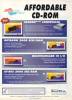
Manufacturer BSC, Germany | Date 1993 | Amiga A2000, A3000, A4000 | Interface Zorro II | Autoconfig ID 2092 / 24 |
- CD-ROM and IDE controller
- no autobooting capability
- half length card - no place for mounting a hard disk on the card
- two 40 pin IDE headers
- supports two IDE or ATAPI devices and two Mitsumi CD-ROM drives at once
- the supported Mitsumi drives are:
- LU-005S single speed
- FX-001S single speed
- FX-001D double speed
- delivered with CD-ROM filesystem

front side

back side
- Tandem.pdf
User's Manual (english/german)
486 kB
- TandemCD-3715.dms
install disk v1.01
tandemcd.device v37.15
236 kB - TandemCD-397.dms
install disk
tandemcd.device v39.7
482 kB - TandemCD-416.dms
install disk
tandemcd.device v41.6
364 kB - oktapus.lha
Aminet
OktaPussy v2.1 (24.11.98)
106 kB - TandemCD.dms
Installer's Heaven
install disk
520 kB
Advert (US)
1994-05
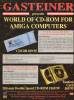
Advert (GB)
1994-08
Manufacturer ICD, USA | Date 1993 | Amiga A500A2000, A3000, A4000 | - - | Interface side expansion portZorro II | Autoconfig ID 2071 / 35 |
- Trifecta LX: SCSI 2 and IDE controllers
- Trifecta EC: IDE controller only
- ZIP sockets accept 8 MB RAM
- autoboot ROM (trifecta.device) - can be disabled with a switch
- autoconfiguring of the memory can be disabled with a switch
- 50 pin external SCSI connector (LX)
- A500 version:
- connects to the side expansion port
- GVP compatible mini slot for GVP's PC emulator board
- own power supply
- Zorro II version:
- does not work in A3000 / A4000

front side
- ICDPrepHD-40.dms
install disk v4.0
ICDPrepHD v4.0, adide.device v4.0r1, adscsi.device v4.0r1, icddisk.device v3.5r1, trifecta.device v4.0r1
117 kB - ICDPrepHD-42.dms
install disk v4.2
ICDPrepHD v4.2, adide.device v4.0r1, adscsi.device v4.0r1, icddisk.device v3.5r1, trifecta.device v4.0r1
117 kB
Manufacturer Individual Computers, Germany | Date 2000 | Amiga A2000, A3000, A4000 | Interface Zorro II | Autoconfig ID 4626 / 23 |
- Ethernet interface
- Realtek 8019AS chipset
- 10Base2 and 10BaseT connectors
- automatic detection of the used connector
- 10 Mbit transfer rate (20 Mbit fullduplex on twisted-pair)
- 16 kB databuffer
- autoprefetch
- automatic polarity correction for 10BaseT
- Noise Filter Bus Interface ensures proper function in heavy-loaded Zorro systems
- SANA 2 driver (MNI driver is in development)
- supported by NetBSD
- expansion ports
- 26 pin expansion port compatible with the one on the Buddha/Catweasel controllers
- two clock ports for A1200 expansions
- two IDE ports: 3,5" and 2,5" - as free add-ons to the X-Surf
- can be activated by the IDE-fix software package
- autobooting is not possible with these ports
- the timing is not configurable
- preemptive use of IDE devices - necessary for CD-writers - is impossible
- all expansion ports are independent from each other and can be used at the same time

front side

back side
- xsurf.lha
Individual Computers
Sana2 driver v1.2
31 kB - xsurfide.lha
Individual Computers
IDE driver v1.04
16 kB
Manufacturer Individual Computers, Germany | Date 2002 | Amiga A2000, A3000, A4000 | Interface Zorro II | Autoconfig ID 4626 / 23 |
- Ethernet interface
- Realtek 8019AS chipset
- 10BaseT connector
- 10 Mbit transfer rate
- fullduplex and supports auto-negotiation
- 16 kB databuffer
- autoprefetch
- automatic polarity correction
- Noise Filter Bus Interface ensures proper function in heavy-loaded Zorro systems
- SANA 2 and PPPoE drivers (MNI driver is in development)
- supported by NetBSD
- expansion ports
- 26 pin expansion port compatible with the one on the Buddha/Catweasel controllers
- two clock ports for A1200 expansions
- two IDE ports: 3,5" and 2,5"
- can be activated by the IDE-fix software package
- autobooting is not possible with these ports
- the timing is not configurable
- preemptive use of IDE devices - necessary for CD-writers - is impossible
- all expansion ports are independent from each other and can be used at the same time

front side

back side
- X-Surf2_deutsch.pdf
Individual Computers
installation guide (german)
90 kB - X-Surf2_english.pdf
Individual Computers
installation guide (english)
85 kB
- dsl-rel2.lha
Individual Computers
DSL (PPPoE) driver
104 kB - xsurfide.lha
Individual Computers
IDE driver v1.04
16 kB
Manufacturer Individual Computers, Germany | Date 2007 | Amiga A2000, A3000, A4000 | Interface Zorro II | Autoconfig ID 4626 / 23 |
- Ethernet interface
- Realtek 8019AS chipset
- 10Base2 and 10BaseT connectors
- automatic detection of the used connector
- 10 Mbit transfer rate (20 Mbit fullduplex on twisted-pair)
- 16 kB databuffer
- autoprefetch
- automatic polarity correction for 10BaseT
- Noise Filter Bus Interface ensures proper function in heavy-loaded Zorro systems
- SANA 2 driver (MNI driver is in development)
- supported by NetBSD
- expansion ports
- 26 pin expansion port compatible with the one on the Buddha/Catweasel controllers
- two clock ports for A1200 expansions
- one IDE port: 3,5" (40 pin header) - as free add-on to the X-Surf
- can be activated by the IDE-fix software package
- autobooting is not possible with these ports
- the timing is not configurable
- preemptive use of IDE devices - necessary for CD-writers - is impossible
- all expansion ports are independent from each other and can be used at the same time