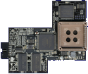
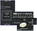
Manufacturer Individual Computers, Germany | Date 2008/2009 | Amiga A1200, A4000, CD32 | Interface Lisa chip |
- flicker-fixer
- with a maximum input pixel clock of 28 MHz, all Amiga video modes up to Super Hires are supported and flicker-fixed (with the exception of the A2024 mode)
- picture refresh rate of at least 60 Hz for all screen modes, resulting in a maximum output pixel clock of 71 MHz
- 24 bit color support (16.7 million colors)
- supports interlaced and progressive scan input modes
- output modes are always progressive scan
- two output modes can be chosen:
- Async mode: output pixel clock of Amiga modes are multiplied 2.5 times
- Vertical Sync mode: exact double of Amiga mode pixel clock (eliminates tearing effects)
- clips only onto the Lisa chip on motherboard, no soldering required
- gets power and all signals from this chip
- sync signals are derived from the inter-chip communication of the AGA chipset
- HD15 VGA connector
- supports border blanking
- 16 megabyte SDRAM
- SDRAM is single-ported, thus reading and writing is decoupled by two FIFO buffers and a dual-port SDRAM controller running at 111 MHz
- only 12 MB are used, 4 MB stay free
- memory layout of 2048x2048 pixels (= maximum resolution)
- compatible to Genlocks
- no passthrough mode (all resolutions are flicker-fixed)
- FPGA based design with FlashROM
- Emergency Mode (emergency disk needed) in case a FlashROM update went wrong
- low heat dissipation due to 2.5V/3.3V design (only the voltage regulator is 5V)
- boot screen, shown for a pre-defined time - in case important information is displayed (e.g. Guru / Error Screen, Early Startup Menu), this time is reduced
- no driver needed, however additional screenmodes are supported:
- HighGFX (1024×786)
- HD720 (1280×720)
- Indivision AGA 1200
- cutouts in the board allow installation of other internal A1200 components like IDE-Fix Express and the Lyra 1200 keyboard adaptor - tight design, so boards may touch on certain A1200 board revisions
- first revision boards were prone to snapping from the Lisa socket, so later revisions had the socket on the Indivision board machine finished
- Indivision AGA 4000
- this is a follow-up design to the Indivision AGA 1200, offering the same features while having a different board layout to fit in A4000D and CD32
- 10nF capacitors have been added to the PLLs
- two (instead of one) TTL drivers for the VGA Sync wires
- prototype board is white, the final version has a blue PCB
 Amiga Hardware Database


