Search Result
14 expansions found
Manufacturer TOMS, Poland | Date 1996 | Amiga CD32 | Interface trapdoor slot |
- Interface Extension
- simple expansion that just provides two connectors
- slim external box, plugs into the rear expansion connector
- interfaces
- 1× video DB23 male, analog RGB
- 1× external floppy DB23 female
- notes
- no passthrough connector, i.e. parallel installation of the FMV module is not possible
Manufacturer Eureka, Netherlands | Date 1994 | Amiga CD32 | Interface AUX port |
- links the CD32 to the serial port of any Amiga
- allows the Amiga to see the CD32 as a standard CD-ROM, though it provides painfully slow data transfers compared to a locally installed CD drive
- connects to the CD32 Aux port
- MIDI-In, MIDI-Out, MIDI-Thru connectors
- the MIDI ports are accessible from the Amiga side too
- three status LEDs showing MIDI Recieve, CD32 Send and Host Send
- the control pad emulates the mouse
- Scala driver - controls audio or video CD playback
- Communicator I
- serial cable belongs to the Communicator unit
- data rates up to 115200 bps (default is 9600, reliable up to 76800)
- A2000 keyboard connector
- Lite version lacks the MIDI and keyboard connectors
- Communicator II
- serial cable is detachable with an RJ11 (telephone type) connector
- data rates up to 210000 bps
- more reliable transfers
- better compatibility with ISO-9660 CDs
- A2000 and A4000 keyboard connectors
- Lite version lacks the MIDI and keyboard connectors and the status LEDs

front side
Manufacturer C.D. Express, Italy | Date 1995 | Amiga CD32 | Interface trapdoor slot, AUX port, joystick port |
- Arcade System
- a CD32 with a JAMMA Adapter board to allow the usage in Arcade cabinets
- expansion consists of a re-labelled CD32, an expansion board and the JAMMA adaptor
- all components are mounted on a baseplate
- Expansion Connector Board
- interconnects JAMMA Adaptor board via 2 ribbon cables and a power supplying cable
- provides RGB video and I/O headers
- plugs into rear expansion port
- no passthrough connector, rules out FMV module
- JAMMA Adapter Board
- connects with two ribbon cables and power cable to the expansion connector board, and to the CD32 directly with audio cable and joystick ribbon cable
- connectors: 1× RGB video (header), 1× I/O (header), 1× joystick/mouse (header), 2× Cinch cable (cable soldered to bottom side), 1× power supply cable (soldered to bottom side)
- two volume potentiometers
- certain revisions are supplied with extra adaptor board that plugs between expansion connector board and the I/O header
- Notes
- only a small number of games were developed for the Cubo CD32, mostly with italian localization
- games:
- without JAMMA board, the joypad trigger buttons can be used for "insert coin" and "start"
| Candy Puzzle | 1995 | Puzzle Game (Puzzle Bubble clone) |
| Harem Challenge | 1995 | Adult Card Game |
| Laser Quiz | 1995 | Quiz Game |
| Laser Quiz France | 1995 | Quiz Game |
| Laser Quiz 2 | 1995 | Quiz Game |
| Laser Strixx | 1995 | |
| Magic Premium | 1996 | Poker Game |
| Odeon Twister | ||
| Odeon Twister 2 | 1999 | |
| Gangster Pursuit | ||
| Camel Racer |

front side

back side

top side

CD32 base unit, top side

CD32 base unit, bottom side

base plate, top side

base plate w/ cable arrangement, top side

Expansion Connector Board, front side

JAMMA Adapter Board, front side

JAMMA Adapter Board, back side

extra Adapter Board, front side

extra Adapter Board, back side
Manufacturer Commodore, USA | Date 1994 | Amiga CD32 | Interface trapdoor slot | Autoconfig ID 514 / 106 |
- MPEG video decoder
- allows the playing of CD-i Digital Video or Video CDs (MPEG 1)
- C-Cube video decoder and LSI-Logic audio decoder chip
- the MPEG animation can be genlocked with the Amiga graphics
- plugs into the rear expansion port
- limits the maximum possible amount of Fast RAM to 4 MB
- can be used with the Paravision SX-1 but not with the DCE SX32 / SX32 Pro

Board, front side

Board, back side

Case, front side
Manufacturer Index Information / Analogic Computers UK, UK | Date 1995 | Amiga CD32 | Interface trapdoor slot | Autoconfig ID 2206 / 1 |
- Disk Drive
- designed specifically for the Wall Street Institute language school
- during the language course students attended computer based training on CD32s with fWSI
- the CD contained the multimedia training software, while the fWSI floppy drive allowed the students to save their progress
- 3.5" 1.44 MB floppy drive
- DB25 parallel port
- DB15 Video Output connector
- battery backed up clock
- plugs into the rear expansion port
- Notes
- Pin assignment of Video Output connector for SCART cable
| fWSI Video Connector Pin |
SCART Pin |
Signal Description |
| 3 | 17 | Composite Video Output Ground / Sync Output Ground |
| 4 | 13 | Red Ground |
| 5 | 9 | Green Ground |
| 6 | 20 | Composite Video Input / Sync Input |
| 14 | 8 | Function Switching |
| 15 | 16 | Fast Switching |
| GND | 7+11+15+ 18+19 |
Ground |
 - Exterior front side")
Exterior, front side
 - Exterior rear side")
Exterior, rear side
 - Exterior rear side")
Exterior, rear side
 - Exterior front side")
Exterior, front side
 - Exterior top side")
Exterior, top side
 - Main Board front side")
Main Board, front side
 - Main Board back side")
Main Board, back side
 - RTC Board front side")
RTC Board, front side
 - RTC Board back side")
RTC Board, back side
 - Audio Board front side")
Audio Board, front side
 - Audio Board back side")
Audio Board, back side
- fWSI-652.dms
Demo and Entrance Test Disk
WSI_Demo 6.52 (15.4.96)
325 kB
Manufacturer Individual Computers, Germany | Date 2008/2009 | Amiga A1200, A4000, CD32 | Interface Lisa chip |
- flicker-fixer
- with a maximum input pixel clock of 28 MHz, all Amiga video modes up to Super Hires are supported and flicker-fixed (with the exception of the A2024 mode)
- picture refresh rate of at least 60 Hz for all screen modes, resulting in a maximum output pixel clock of 71 MHz
- 24 bit color support (16.7 million colors)
- supports interlaced and progressive scan input modes
- output modes are always progressive scan
- two output modes can be chosen:
- Async mode: output pixel clock of Amiga modes are multiplied 2.5 times
- Vertical Sync mode: exact double of Amiga mode pixel clock (eliminates tearing effects)
- clips only onto the Lisa chip on motherboard, no soldering required
- gets power and all signals from this chip
- sync signals are derived from the inter-chip communication of the AGA chipset
- HD15 VGA connector
- supports border blanking
- 16 megabyte SDRAM
- SDRAM is single-ported, thus reading and writing is decoupled by two FIFO buffers and a dual-port SDRAM controller running at 111 MHz
- only 12 MB are used, 4 MB stay free
- memory layout of 2048x2048 pixels (= maximum resolution)
- compatible to Genlocks
- no passthrough mode (all resolutions are flicker-fixed)
- FPGA based design with FlashROM
- Emergency Mode (emergency disk needed) in case a FlashROM update went wrong
- low heat dissipation due to 2.5V/3.3V design (only the voltage regulator is 5V)
- boot screen, shown for a pre-defined time - in case important information is displayed (e.g. Guru / Error Screen, Early Startup Menu), this time is reduced
- no driver needed, however additional screenmodes are supported:
- HighGFX (1024×786)
- HD720 (1280×720)
- Indivision AGA 1200
- cutouts in the board allow installation of other internal A1200 components like IDE-Fix Express and the Lyra 1200 keyboard adaptor - tight design, so boards may touch on certain A1200 board revisions
- first revision boards were prone to snapping from the Lisa socket, so later revisions had the socket on the Indivision board machine finished
- Indivision AGA 4000
- this is a follow-up design to the Indivision AGA 1200, offering the same features while having a different board layout to fit in A4000D and CD32
- 10nF capacitors have been added to the PLLs
- two (instead of one) TTL drivers for the VGA Sync wires
- prototype board is white, the final version has a blue PCB

Indivision AGA 1200, front side

Indivision AGA 1200, back side

Indivision AGA 4000 Prototype Board, front side

Indivision AGA 4000 Prototype Board, back side
Manufacturer Individual Computers, Germany | Date 2012/2013 | Amiga A1200, A4000T, A4000, CD32 | Interface Lisa chip |
- flicker-fixer
- all Amiga video modes up to Super Hires are supported and flicker-fixed (with the exception of the A2024 mode)
- picture refresh rate of at least 60 Hz for all screen modes, resulting in a maximum output pixel clock of 71 MHz
- 24 bit color support (16.7 million colors)
- supports interlaced and progressive scan input modes
- output modes are always progressive scan
- two output modes can be chosen:
- Async mode: output pixel clock of Amiga modes are multiplied 2.5 times
- Vertical Sync mode: exact double of Amiga mode pixel clock (eliminates tearing effects)
- clips only onto the Lisa chip on motherboard, no soldering required
- gets power and all signals from this chip
- sync signals are derived from the inter-chip communication of the AGA chipset
- DVI-I connector
- supports border blanking
- 16 megabyte SDRAM
- SDRAM is single-ported, thus reading and writing is decoupled by two FIFO buffers and a dual-port SDRAM controller running at 111 MHz
- only 12 MB are used, 4 MB stay free
- memory layout of 2048x2048 pixels (= maximum resolution)
- compatible to Genlocks
- no passthrough mode (all resolutions are flicker-fixed)
- FPGA based design with FlashROM
- Emergency Mode (emergency disk needed) in case a FlashROM update went wrong
- low heat dissipation due to 2.5V/3.3V design (only the voltage regulator is 5V)
- boot screen, shown for a pre-defined time - in case important information is displayed (e.g. Guru / Error Screen, Early Startup Menu), this time is reduced
- no driver needed, however additional screenmodes are supported:
- HighGFX (1024×786)
- HD720 (1280×720)
- Xtreme (1280×1024)
- SuperPlus (800×600)
- config tool provided to update flash memory and make adjustments to the output
- the socket on the board had to be machined to fit properly on the Lisa chip
- compared to the predecessor, the board features a faster FPGA, faster memory and more flexible pixel clocks - however the main features stay the same
- Indivision AGA MK2 1200 / A4000T (2012)
- DVI connector is located on a small PCB
- Indivision AGA MK2 4000 / CD32 (2012)
- DVI connector is located on a small PCB
- has a different board layout to fit in A4000D and CD32, but has the same features as Indivision AGA MK2 1200 / A4000T
- Indivision AGA MK2cr 1200 / A4000T (2013)
- cost reduced version:
- the components from the auxiliary PCB were moved to the Indivision board
- custom made DVI-I connector (molded type) connects to the board
- doesn't fit into the A4000T without modification: due to the changed connector for the DVI ouput, the board interferes with the electrolytic capacitor CE164C in the A4000T - this has to be replaced by a lower profile ceramic type to be able to fit the board
- custom tooling for the socket pins results in a firmer hold on the Lisa chip
Manufacturer HDP Electronics, Poland | Date 1995 | Amiga CD32 | Interface trapdoor slot |
- Interface Extension
- provides additional interfaces to the CD32
- external box, plugs into the rear expansion connector
- interfaces
- 1× parallel DB25 female, Centronics
- 1× video DB23 male, analog RGB
- 1× external floppy DB23 female
- 1× internal 40 pin IDE header for a 3.5" hard disk
- 1× 5 pin DIN connector for an IBM-AT keyboard
- notes
- the serial, parallel and floppy ports are controlled by two onboard CIA chips
- the HDD is intended to be placed externally, a small cutout at back side exists to feed through a IDE ribbon cable
- expansion doesn't provide power for the hard disk, i.e. an external power supply is needed
- disable switch at the back plate
- no passthrough connector, i.e. parallel installation of the FMV module is not possible
- no serial connector (CD32 AUX port may be used)
- genlock compatible
Manufacturer Elsat, Poland | Date 1995 | Amiga CD32 | Interface trapdoor slot | Autoconfig ID 17740 / 1,3 |
- turns the CD32 into an A1200
- external box placed under the CD32, connects to the rear expansion connector
- passthrough connector, the FMV module still fits inside the CD32
- memory
- one 72 pin SIMM socket
- accepts up to 4 MB RAM with the FMV module installed or 8 MB without it
- supports 2, 4 or 8 MB SIMMs
- memory disable switch
- interfaces
- serial DB25 male, RS232
- parallel DB25 female, Centronics
- video DB23 male, analog RGB
- floppy DB23 female
- internal 34 pin floppy header
- internal 40 pin IDE header
- 5 pin DIN connector for an IBM-AT keyboard
- power connector for optional external A500/A1200/A600 power supply
- notes
- optional FPU
- place for a 3.5" hard disk inside the case
- 880 kB floppy drive
- supports up to three external floppy drives
- disables the Aux port so only IBM-AT keyboards can be used
- battery backed up clock
- jumper settings
| Jumper | Configuration | Setting |
| JP1, JP2 | FPU clock | Asynchronous / Synchronous |
| JP3 | Real Time Clock Write | Enable / Disable |
| JP4 | Hard Disk Reset | Enable / Disable |
| JP5, JP6 | Memory Size | 0 MB - OFF OFF 2 MB - ON OFF 4 MB - ON ON 8 MB - OFF ON |
| JP12 | External Floppy | Left - DF0:, Right - DF1: |
| JP13 | Expansion RAM | Enable / Disable |
 - Case front side")
Case, front side
 - Board front side")
Board, front side
 - Board back side")
Board, back side
 - Connector board front side")
Connector board, front side
- ProModule.dms
Tool Disk (polish)
AT-bus Info v1.21, HDPrep v1.14, HDFormat v1.08, Transformer v1.08, MemoryTest v1.39
145 kB - ProModule_en.dms
Tool Disk (english)
AT-bus Info v1.21, HDPrep v1.15, AddMem v1.0
94 kB
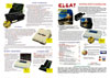
Advert (PL)
1996-06
Manufacturer DCE, Germany | Date 1995 | Amiga CD32 | Interface trapdoor slot | Autoconfig ID 8704 / 02157 / 0 |
- turns the CD32 into an A1200
- connects to the rear expansion connector into the place the FMV module
- memory
- one 72 pin SIMM socket accepts up to 8MB RAM
- supports 1, 2, 4 or 8 MB SIMMs, 80 ns or faster
- interfaces
- serial DB25 male, RS232
- parallel DB25 female, Centronics
- external floppy DB23 female
- video DB23 male, analog RGB
- VGA HD15 male, analog RGB
- internal 44 pin IDE header
- notes
- the serial, parallel and floppy ports are controlled by two onboard CIA chips
- mounting holes for a 2.5" hard disk
- supports up to three floppy drives
- battery backed up clock
- disable jumper

Main board, front side

Main board, back side

Connector board, front side

Connector board, back side
Manufacturer DCE, Germany | Date 1996 | Amiga CD32 | Interface trapdoor slot | Autoconfig ID 8704 / 02157 / 0 |
- turns the CD32 into an A1200
- connects to the rear expansion connector into the place the FMV module
- the board is little over half the size of SX 32 Mk1
- lower power consumption
- memory
- one 72 pin SIMM socket accepts up to 8MB RAM
- supports 1, 2, 4 or 8 MB SIMMs, 80 ns or faster
- improved memory controller (over SX 32 Mk1) which is more tolerant with SIMM specifications
- interfaces
- serial DB25 male, RS232
- parallel DB25 female, Centronics
- external floppy DB23 female
- video DB23 male, analog RGB
- VGA HD15 male, analog RGB
- internal 44 pin IDE header
- notes
- optional PLCC FPU up to 33 MHz
- the serial, parallel and floppy ports are controlled by two onboard CIA chips
- mounting holes for a 2.5" hard disk
- the CD LED shows hard disk activity
- supports up to three floppy drives
- battery backed up clock
- disable jumper

bottom side

top side
Manufacturer DCE, Germany | Date 1996 | Amiga CD32 | Interface trapdoor slot | Autoconfig ID 2157 / 0 |
- turns the CD32 into an accelerated A1200
- connects to the rear expansion connector into the place the FMV module
- processor
- 68030 @ 25 / 50 MHz, PGA
- optional 68882 @ 25 / 50 MHz, PGA
- memory
- one 72 pin SIMM socket accepts up to 64 MB RAM
- zero wait state for 50 ns or faster RAM
- one wait state for slower RAM
- interfaces
- serial DB25 male, RS232
- parallel DB25 female, Centronics
- external floppy DB23 female
- video DB23 male, analog RGB
- VGA HD15 male, analog RGB
- internal 44 pin IDE header
- notes
- buffered IDE interface
- DMA transfers via the Akiko chip
- the serial, parallel and floppy ports are controlled by two onboard CIA chips
- mounting holes for a 2.5" hard disk
- supports up to three floppy drives
- battery backed up clock
- disable switch

Main board, front side

Main board, back side
Connector board, front side
Connector board, back side
Manufacturer Paravision / Microbotics, USA | Date 1994 | Amiga CD32 | Interface trapdoor slot | Autoconfig ID 1010 / 1291010 / 193 |
- turns the CD32 into an A1200
- external box (15 × 20 × 6 cm), plugs into the rear expansion connector
- passthrough connector, the FMV module still fits inside the CD32
- memory
- one 72 pin SIMM socket
- accepts up to 4 MB RAM with the FMV module installed or 8 MB without it
- supports 1, 2, 4 or 8 MB SIMMs, 80 ns or faster
- when 8 MB is installed, it appears as two blocks of 4 MB
- memory disable jumper
- interfaces
- serial DB9 male, RS232
- parallel DB25 female, Centronics
- video DB23 male, analog RGB
- external floppy DB23 female
- internal 44 pin IDE header
- external DB37 IDE connector
- 6 pin mini-DIN audio input for mixing external audio and CD32 sound
- 5 pin DIN connector for an IBM-AT keyboard
- notes
- the serial, parallel and floppy ports are controlled by two onboard CIA chips
- place for a 2.5" hard disk inside the case
- boot delay jumper - adds a 10 second delay before booting for slow hard drives
- supports up to three floppy drives
- disables the Aux port's serial connection feature - it can be used to attach Amiga keyboards only
- battery backed up clock
- disable switch - leaves alive the RGB port, the memory and the clock
- jumper settings
| 1 - | SIMM type: ON - double sided, OFF - single sided |
| 2 - | SIMM size: ON - 4 or 8 MB, OFF - 1 or 2 MB |
| 3 - | RAM autoconfig: ON - disabled |
| 4 - | autoboot delay: ON - enabled |
| 5 - | AT keyboard: ON - two Alt keys, OFF - right Alt key mapped to right Control key |

Main board, front side

Main board, back side

Connector board, front side

Connector board, back side
- SX1.dms
tool disk (RDPrep v3.91, RDPrepX v2.90)
148 kB
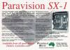
Advert (AU)
1994-10
Manufacturer Taurus Ventures, Canada | Date 1994 | Amiga CD32 | Interface AUX port |
- external modem
- 2400 bps Hayes compatible modem
- originally developed for the TeleView home banking system of the canadian VanCity Savings Credit Union bank
- hand-held remote controller for entering alphanumeric characters (and operating the banking software)
- the built-in infrared receiver can be adjusted to accept signals from a variety of third party remote control units
- the software allowed the users to do a variety of common financial transactions, including bill payment, transfer of funds between accounts, up to the minute online account statements and balances, interest and investment rate queries
- connects to the AUX port
- passthrough connector for keyboards
- the modem is also suitable for multiplayer gaming

Modem, front side

Modem, back side

Modem, bottom side

Remote Control, front side

Remote Control, back side