 Amiga Hardware Database
Manufacturer “Omni-Eureka Electronics”
11 expansions in database
Manufacturer Pyramid / Omni-Eureka Electronics, Taiwan | Date 1992 | Amiga any Amiga | Interface serial port |
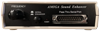
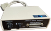
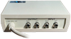
- Audio Equalizer
- boosts certain parts of the frequency range to "enhance" the Amiga sound output
- frequency response can be controlled with potentiometer on the front plate
- audio output 2× RCA socket
- audio input 2× RCA socket
- power supply via serial port
- serial interface pass-through connector on the front plate allows connection of other serial devices at the same time
- bypass switch disables filter function and passes through original sound unaltered
Manufacturer Pyramid / Omni-Eureka Electronics, Taiwan | Amiga any Amiga | Interface parallel port |
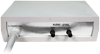
- Sound Sampler
- external sound sampler for the parallel port
- samples in stereo signals in 8 bit
- audio inputs on the front plate:
- 1× stereo line level (2 RCA sockets)
- 1× microphone (6.35mm jack)
- level adjustment potentiometers (manual gain control) for left and right channel on the back plate
- desktop case with a fixed parallel cable
- parallel port is not passed through
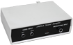
front side
back side
- Pyramid_Expansions.pdf
Installation Guide
5.6 MB
Manufacturer Pyramid / Omni-Eureka Electronics, Taiwan | Date 1992 | Amiga A500 | Interface trapdoor slot, Gary socket |
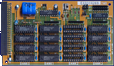
- 16 DIP sockets accept up to 2 MB RAM
- accepts 256k×4 DIPs in groups of four
- 1 MB can be set either as Chip or Fast RAM
- disable jumper
- the main board connects to the trapdoor slot
- an adaptor board connects to Gary's socket
- battery backed up clock
front side
back side

Advert (UK)
1992-03
Advert (DE)
1992-04
Manufacturer Pyramid / Omni-Eureka Electronics, Taiwan | Date 1992 / 1994 | Amiga A500 | Interface trapdoor slot, Gary socket |
- Chip and/or Fast RAM expansion
- 2 or 4 MB RAM
- 1992:
- 32 DIP sockets
- takes 256k×4 DIPs in groups of 16
- 1994:
- two 72 pin SIMM sockets
- takes 1 or 2 MB SIMMs, sizes cannot be mixed
- the main board connects to the trapdoor slot
- an adaptor board connects to Gary's socket and is plugged into header JP1 on the main board
- 1 MB can be used either as Chip or Fast RAM, depending on the setup
- disable switch
- battery backed up clock
- RAM Setups
- Mode 1: FastRAM expansion only
- no CPU board needed, no soldering required
- jumper JP2 on expansion main board set to "FAST"
- Mode 2: FastRAM and 512kB ChipRAM expansion
- no CPU board needed, but soldering required
- JP2 on the A500 mainboard has to be cut and a cable has to be soldered that connects the middle pad of that jumper with JP3 on the Gary adaptor board
- jumper JP2 on expansion main board set to "CHIP"
- Mode 3: FastRAM and 512kB ChipRAM expansion
- optional CPU board required, no soldering needed
- the CPU board plugs into 68000 socket, the CPU is replaced onto the board
- supplied cable connects the headers JP1 on CPU board and JP2 on Gary adaptor board
- jumper JP2 on expansion main board set to "CHIP"
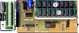
front side
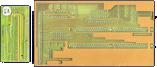
back side
- Eureka4MB_de.pdf
Benutzerhandbuch
936 kB - Eureka4MB.pdf
User Manual
127 kB
Advert (UK)
1992-03
Advert (DE)
1992-04
Manufacturer Pyramid / Omni-Eureka Electronics, Taiwan | Date 1992 | Amiga A500 | Interface trapdoor slot |
- RAM Expansion
- 512 kB RAM
- four 256k×4 DIPs
- battery backed up clock
- connects to the trapdoor slot
Advert (UK)
1992-03
Advert (DE)
1992-04
Manufacturer Pyramid / Omni-Eureka Electronics, Taiwan | Date 1992 | Amiga any Amiga | Interface parallel port |
- Handy Scanner
- scans monochrome and grey shades
- 400 dpi optical resolution
- status LED
- scan start button
- controls: contrast, resolution (100/200/300/400 dpi), bit depth
- Scanner Interface
- interface box for desktop placement
- connects to the parallel port
- for use with A1000 an adaptor is needed
- scanner connector on front plate
- passthrough connector - simultaneous usage of scanner and other parallel devices is not possible, a button on the front plate switches between scanner and passthrough mode
- external power supply
- Notes
- this is expansion was also sold as Telmex Handy Scanner
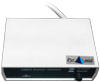
top side
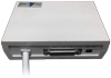
back side
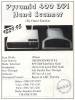
Advert (US)
1992-11
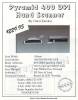
Advert (US)
1992-12
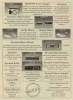
Advert (US)
1993-04
Manufacturer Pyramid / Omni-Eureka Electronics, Taiwan | Amiga any Amiga | Interface serial port |
- MIDI Interface
- external MIDI interface for the serial port
- offers 1× MIDI-IN, 2× MIDI-THRU and 2× MIDI-OUT
- desktop case with a fixed serial cable
- serial port is passed through, a switch on the back side selects between MIDI interface and pass-through operation
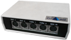
front side
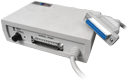
back side
- Pyramid_Expansions.pdf
Installation Guide
5.6 MB
Manufacturer Pyramid / Omni-Eureka Electronics, Taiwan | Amiga any Amiga | Interface mouse port |
- Joystick Port Switcher
- adapter that automatically switches between mouse and joystick
- plugs into mouse port with a fixed cable
- two DB9 ports for mouse and joystick at the front plate
- active device is enabled by pressing mouse button respective fire button
- LED on the front plate indicates active port
- desktop case
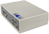
front side
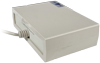
back side
- Pyramid_Expansions.pdf
Installation Guide
5.6 MB
Manufacturer Omni-Eureka Electronics / Pyramid, Taiwan | Date 1992 | Amiga A500, A500+ | Interface trapdoor slot |
- A500
- 512 kB RAM
- two versions:
- RAM-512K - four 256k×4 chips
- RAM-512K.C - sixteen 256k×1 chips
- connects to the trapdoor slot
- battery backed up clock
- A500+
- 1 MB RAM
- eight 256k×4 chips
- connects to the trapdoor slot
- Notes
- features the same OEM hardware as the Telmex Mini RAM 500

front side

back side
Advert (US)
1993-04
Manufacturer Omni-Eureka Electronics / Pyramid, Taiwan | Date 1993 | Amiga A600 | Interface trapdoor slot |
- 1 MB RAM
- two versions:
- rev A - eight 128k×9 chips
- rev B - twelve 256k×3 chips
- connects to the trapdoor slot
- battery backed up clock
- disable switch
- Notes
- features the same OEM hardware as the Telmex Mini RAM 600

Rev B, front side

Rev A, front side

Rev A, back side

Rev B, back side
Advert (US)
1993-04
Manufacturer Pyramid / Omni-Eureka Electronics, Taiwan | Date 1993 | Amiga A1200 | Interface trapdoor slot | Autoconfig ID 2640 / 10 |
- Memory Expansion
- provides up to 8 MB FastRAM
- optional PGA FPU 68881/68882, clocked at 14.3 MHz (synchronous to CPU clock) or up to 50 MHz with oscillator installed (asynchronous)
- one 72 pin SIMM socket accepts 2, 4 or 8 MB RAM
- with 8 MB RAM, the board conflicts with the PCMCIA port - the used memory can be limited to 4 MB for that reason
- battery backed up clock
- disable switch
- Jumper Settings
| JP1 (1-2) | JP1 (3-4) | JP1 (5-6) | JP2 | Function |
| ON | OFF | ON | OFF | 1 MB |
| OFF | ON | ON | OFF | 2 MB |
| ON | ON | ON | OFF | 4 MB |
| OFF | OFF | OFF | OFF | 8 MB (not PCMCIA compatible) |
| OFF | OFF | OFF | ON | 8 MB installed, only 4 MB used (PCMCIA compatible) |
| JP3 | Function |
| 1-2 | FPU - synchronous operation (14.3 MHz) |
| 2-3 | FPU - oscillator |

Rev B, front side
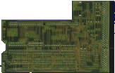
Rev B, back side
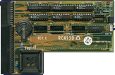
Rev C, front side
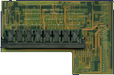
Rev C, back side
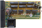
Rev C, front side
- RCA120_de.pdf
Bedienungsanleitung
31 kB - RCA120_en.pdf
user manual
25 kB