Search Result
11 expansions found
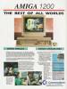
Company Commodore, USA | Date 1992 |
- full description is in the models section
- short description
- 68EC020 @ 14.28 MHz
- 2 MB Chip RAM
- AGA chip set
- built-in IDE controller

Rev 1D1, front side

Rev 1D1, back side

Rev 2B, front side

Rev 2B, back side
- A1200-german.pdf
user manual (german)
1506 kB

Advert (US)
1998-03

Advert (US)
1993-03
Advert (AU)
1993-06

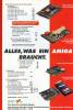
Advert (DE)
1993-06
Company Petsoff, Finland | Date 1998 | Amiga A1200 | Interface clock port |
- DSP
- Motorola DSP56002 @ 37 (underclocked 40 MHz) or 73.7 MHz (overclocked from 66 MHz)
- 24 bit data bus
- fully programmable using the supplied software
- memory
- 96 kB, 24 bit SRAM
- one half of the memory can be addressed in program and X data space, the other half only in Y data space
- zero-waitstate, 12 ns
- audio
- Crystal CS4231A audio codec
- one stereo RCA input
- one stereo 3.5 mm input with optional 20 dB mic amplifier
- one internal CD-ROM input
- one stereo RCA output
- all inputs can be mixed with Delfina's output
- full duplex recording and playback
- AHI support
- notes
- connects to the clock port
- the audio cables are connected directly onto the board, not to the back of the Amiga

front side

back side
- Delfina-415.lha
install disk v4.15
757 kB - delflib416b48.lha
Individual Computers
delfina.library v4.16b48
22 kB
Company Elbox, Poland | Date 1998 | Amiga A1200 | Interface Kickstart socket, Gayle | Autoconfig ID 2206 / 8,16,182206 / 19,24,53 |
- Fast EIDE controller
- supports PIO0, PIO3 and PIO4 devices
- meets the ATA 3 and Fast ATA 2 specifications
- up to 16.6 MB/s transfer speed
- totally replaces the A1200's IDE controller by attaching to the Gayle and the ROMs
- the ROMs have to be plugged onto the FastATA main board
- a small fly has to be attached to pin 39 of the old IDE header
- small cutout on the board allows access to the clock port for Catweasel users
- three IDE headers:
- two 40 pin, 3.5" (primary and secondary)
- one 44 pin, 2.5" (primary)
- the primary and secondary buses can be accessed at different speeds
- up to four IDE or ATAPI devices can be connected at once
- buffered and cached interface
- reset switch connector
- unconventional handling of >4 GB devices - they are simply split into separate logical 4 GB blocks
- supported by Linux
- variations
- FastATA 1200 Lite / PowerFlyer Junior
- supports 16 bit ATA transfers only
- can be upgraded to full 32 bit FastATA by simply plugging in the upgrade chip
- FastATA 1200 Mk2
- improved firmware in the PLD chips
- newer autoboot ROM
 - front side")
front side
Company Individual Computers, Germany | Date 2008/2009 | Amiga A1200, A4000, CD32 | Interface Lisa chip |
- flicker-fixer
- with a maximum input pixel clock of 28 MHz, all Amiga video modes up to Super Hires are supported and flicker-fixed (with the exception of the A2024 mode)
- picture refresh rate of at least 60 Hz for all screen modes, resulting in a maximum output pixel clock of 71 MHz
- 24 bit color support (16.7 million colors)
- supports interlaced and progressive scan input modes
- output modes are always progressive scan
- two output modes can be chosen:
- Async mode: output pixel clock of Amiga modes are multiplied 2.5 times
- Vertical Sync mode: exact double of Amiga mode pixel clock (eliminates tearing effects)
- clips only onto the Lisa chip on motherboard, no soldering required
- gets power and all signals from this chip
- sync signals are derived from the inter-chip communication of the AGA chipset
- HD15 VGA connector
- supports border blanking
- 16 megabyte SDRAM
- SDRAM is single-ported, thus reading and writing is decoupled by two FIFO buffers and a dual-port SDRAM controller running at 111 MHz
- only 12 MB are used, 4 MB stay free
- memory layout of 2048x2048 pixels (= maximum resolution)
- compatible to Genlocks
- no passthrough mode (all resolutions are flicker-fixed)
- FPGA based design with FlashROM
- Emergency Mode (emergency disk needed) in case a FlashROM update went wrong
- low heat dissipation due to 2.5V/3.3V design (only the voltage regulator is 5V)
- boot screen, shown for a pre-defined time - in case important information is displayed (e.g. Guru / Error Screen, Early Startup Menu), this time is reduced
- no driver needed, however additional screenmodes are supported:
- HighGFX (1024×786)
- HD720 (1280×720)
- Indivision AGA 1200
- cutouts in the board allow installation of other internal A1200 components like IDE-Fix Express and the Lyra 1200 keyboard adaptor - tight design, so boards may touch on certain A1200 board revisions
- first revision boards were prone to snapping from the Lisa socket, so later revisions had the socket on the Indivision board machine finished
- Indivision AGA 4000
- this is a follow-up design to the Indivision AGA 1200, offering the same features while having a different board layout to fit in A4000D and CD32
- 10nF capacitors have been added to the PLLs
- two (instead of one) TTL drivers for the VGA Sync wires
- prototype board is white, the final version has a blue PCB

Indivision AGA 4000 Prototype Board, front side

Indivision AGA 1200, front side

Indivision AGA 1200, back side

Indivision AGA 4000 Prototype Board, back side
Company M-Tec, Germany | Date 1993 | Amiga A1200 | Interface trapdoor slot |
- FPU
- early versions (Neuroth design) have PLCC FPU socket
- later versions (marked as "A1200 Speedup") have PGA FPU socket
- can be clocked either synchronously (14.28 MHz) or asynchronously (up to 50 MHz with oscillator)
- memory
- four 30 pin SIMM sockets for 4 MB RAM
- accepts 1 MB, 80 ns or faster SIMMs in a group of four
- the height of SIMMs cannot be larger than 15 mm
- PCMCIA compatible
- notes
- available with or without battery backed up clock
- lithium battery (not rechargeable)
- clock write protection jumper

front side

front side

front side

back side
- MTec_A1200.pdf
user manual (german)
45 kB
Advert (DE)
1993-08

Advert (DE)
1993-11
Company MicroniK, Germany | Date 1997 | Amiga A1200 | Interface trapdoor slot |
- Micronik Z-1 (6860 rev4.0)
- 5× Zorro II slots
- 4× ISA slots
- Micronik Z-2 (6860 rev4.2)
- 5× Zorro II slots
- 1× extended video slot
- 4× ISA slots
- Micronik Z-2 (6860 rev5.0)
- 5× Zorro II slots
- 1× extended video slot
- 3× ISA slots
- a 72 pin SIMM socket for up to 8 MB RAM
- notes
- the ISA and video slots are inline with Zorro slots
- the video slot can be activated with the optional Video Slot Adapter
- connects to the trapdoor slot - the connector is passed through for accelerator cards
- the boards are part of the Micronik Infinitiv tower system
- 2× 5.25" external drive bays
- 2× 3.5" external drive bays
- 2× 3.5" internal drive bays
- uprated power supply
 - front side")
front side
 - back side")
back side
 - A1200 Adapter front side")
A1200 Adapter, front side
 - A1200 Adapter back side")
A1200 Adapter, back side
Company MicroniK, Germany | Date 1998 | Amiga A1200 | Interface trapdoor slot |
- Micronik Z-1i (6860 rev5.4)
- 5× Zorro II slots
- 1× extended video slot
- 2× PCI slots
- 2× ISA slots
- Micronik Z-2i (6860 rev5.4)
- all features of Micronik Z-1i
- two 72 pin SIMM sockets for up to 8 MB RAM
- notes
- the ISA and video slots are inline with Zorro slots
- the PCI slots cannot be accessed by the Amiga in any way
- the video slot can be activated with the optional Video Slot Adapter
- connects to the trapdoor slot - the connector is passed through for accelerator cards
- the boards are part of the Micronik Infinitiv tower system
- 2× 5.25" external drive bays
- 2× 3.5" external drive bays
- 2× 3.5" internal drive bays
- uprated power supply
 - front side")
front side
Company MicroniK, Germany | Date 1998 | Amiga A1200 | Interface trapdoor slot | Autoconfig ID 3855 / 1 |
- Micronik Z-3i (6860 rev6.2 - 6.3)
- 5× Zorro II/III slots
- 1× extended video slot
- 2× PCI slots
- 1× ISA slot
- 1× A4000 CPU slot - an A4000 processor board is required for Zorro III operation
- a 72 pin SIMM socket for up to 8 MB RAM
- SCSI controller (123.device) with 50 pin internal SCSI header
- Micronik Z-3i Mk2 (6860 rev6.6 - 6.8)
- 5× Zorro II/III slots (the middle slot is Zorro II only)
- 1× extended video slot
- 3× PCI slots
- 2× ISA slot
- 1× A4000 CPU slot - an A4000 processor board is required for Zorro III operation
- SCSI controller - Qlogic FAS216 controller IC, 50 pin internal SCSI header
- notes
- the ISA and video slots are inline with Zorro slots
- the PCI slots cannot be accessed by the Amiga in any way
- the video slot can be activated with the optional Video Slot Adapter
- the Zorro III slots are slower than the A3000 or A4000 slots
- connects to the trapdoor slot - the connector is passed through for accelerator cards
- the board is part of the Micronik Infinitiv tower system
- 2× 5.25" external drive bays
- 2× 3.5" external drive bays
- 2× 3.5" internal drive bays
- uprated power supply
 - front side")
front side
Company Logica, Italy | Date 1994 | Amiga A1200 | Interface trapdoor slot |
- FastRAM expansion
- two 72 pin SIMM sockets accept 8 MB RAM
- supports 1, 2, 4 or 8 MB SIMMs
- possible RAM configurations: 1, 2, 3, 4, 5, 6 and 8 MB
- optional PGA FPU, can be clocked either synchronously (14.28 MHz) or asynchronously (up to 50 MHz)
- for asynchronous clock, an external oscillator in DIP14 or DIP8 package is required (DIP8 oscillator is installed towards the FPU)
- battery backed up clock
- clock write protection
- diagnostics and upgrade ("D&U Slot") connector, to be used in factory for expansion diagnostics and software update by reprogramming
- jumper settings
| Jumper | Configuration | Setting |
| J1 | RAM disable | ON - Disable RAM, OFF - Enable RAM |
| J2..J4 | RAM configuration | see table below |
| J5 | FPU Clock | 1-2 - synchronous, 2-3 - asynchronous (oscillator installed) |
| J6 | Clock Protection | ON - Enable Write Clock, OFF - Disable |
| J2 ON ON ON ON ON OFF OFF OFF OFF OFF |
J3 ON ON ON OFF OFF ON ON OFF OFF OFF |
J4 ON OFF OFF ON OFF ON OFF ON OFF OFF |
SIMM1 1 1 2 2 2 4 4 4 4 8 |
SIMM2 - 1 - 1 2 - 1 2 4 - |
Total 1 2 2 3 4 4 5 6 8 8 |

front side

with RAM installed, front side

back side
- OMega1200.pdf
User Manual (italiano)
1626 kB
- OMega1200.dms
tool disk
646 kB
Company Pyramid | Date 1994 | Amiga A1200 | Interface trapdoor slot |
- processor
- 68EC020 @ 28 MHz QFP, clocked synchronously with the motherboard
- optional PLCC FPU, can be clocked synchronously at 28 MHz, or asynchronously with a separate oscillator
- memory
- one 72 pin SIMM socket accepts up to 8 MB RAM
- supports 1, 2, 4 or 8 MB SIMMs
- notes
- battery backed up clock

front side

back side
Company HK-Computer, Germany | Date 1993 | Amiga A1200 | Interface trapdoor slot |
- optional PLCC or PGA FPU up to 68882 @ 50 MHz
- one 72 pin SIMM socket accepts 8 MB RAM
- supports 1, 2, 4, 8 MB SIMMs
- does not conflict with the PCMCIA address space
- battery backed up clock