Suchergebnis
35 gefundene Erweiterungen
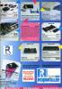
Hersteller Roßmöller, Deutschland | Datum 1990 | Amiga A2000, A3000, A4000 | Schnittstelle ISA |
- 386-Erweiterung für XT-Karte A2088XT
- Installation in einen freien ISA-XT-Steckplatz
- ein Flachbandkabel verbindet 386si und A2088XT
- der 8088 muß von der A2088XT auf den 386si gesteckt werden
- CPU: 80386 SX @ 16 MHz
- 16 kB statisches Cache-RAM
- Steckplätze für max. 8 MB RAM
- zum Teil inkompatibel mit Janus-Software
- Emulation des IBM AT
Werbung (DE)
1990-05
Werbung (DE)
1990-07
Werbung (DE)
1990-09
Hersteller Commodore, USA | Datum 1990 | Amiga A2000, A3000, A4000 | Schnittstelle Zorro II, ISA |
- CPU: NEC V20 @ 4.77 / 7.15 / 9.54 MHz (PLCC)
- die verschiedenen Taktraten sind per Software umschaltbar (Ctrl-S, Ctrl-T, Ctrl-D)
- 640 kB RAM
- 16 kB XT-kompatibles BIOS
- kein Diskettenlaufwerk mitgeliefert - es benutzt das eingebaute 3.5"-Diskettenlaufwerk des Amigas
- das Laufwerk kann entweder von Amiga und PC gleichzeitig oder von einem der beiden exklusiv benutzt werden
- kann jedes andere Amiga-Diskettenlaufwerk nutzen: intern oder extern, DD oder HD, 3.5" oder 5.25"
- Parallel-Schnittstelle und Maus werden vom Amiga emuliert
- Piezo-Beeper
- Emulation des IBM XT

Vorderseite

Rückseite
- CBM-PCInstall-334.dms
install disk v1.02
janus.library v33.4 (11.09.1989)
328 kB - CBM-PCJanus.zip
PC Software
99 kB
Hersteller Commodore, USA | Datum 1986 | Amiga A2000, A3000, A4000 | Schnittstelle Zorro II, ISA | Autoconfig-ID 513 / 1 |
- CPU: 8088 @ 4.77 MHz
- FPU: 8087, optional
- 512 kB RAM
- 16 kB XT-kompatibles BIOS
- 360 kB 5.25"-Laufwerk im Lieferumfang
- benutzt Amiga-Diskettenlaufwerke am externen Anschluß mit 720 kB
- CGA-Bildschirmmodi 640x200x2 oder 320x200x4 per Jumper wählbar
- nutzt die parallelen Schnittstellen des Amigas
- kann mittels Roßmöller 386si auf 386 aufgerüstet werden
- Emulation des IBM XT

Vorderseite

Rückseite
- A2088-A2286.pdf
user's guide
38.0 MB - A2088XT.pdf
user manual (german) + addendum
734 kB
- A2088Turbo.lha
speedup modification
7 kB - CBM-AmigaJanus21-3683.dms
install disk v2.1
janus.library v36.83 (21.8.91)
280 kB - CBM-PCInstall-322.dms
install disk
janus.library v32.2 (25.04.1986)
182 kB - CBM-PCInstall-331.dms
install disk
janus.library v33.1b5 (25.10.1988)
324 kB - CBM-PCInstall-334.dms
install disk v1.02
janus.library v33.4 (11.09.1989)
328 kB - CBM-PCJanus.zip
PC Software
99 kB
Hersteller Commodore, USA | Datum 1989 | Amiga A2000, A3000, A4000 | Schnittstelle Zorro II, ISA | Autoconfig-ID 513 / 2 |
- CPU: 80286 @ 8 MHz
- FPU: 80287, optional
- 1 MB RAM
- 16 kB AT-kompatibles BIOS
- Batterieanschluß, um die BIOS-Einstellungen zu sichern
- 1.2 MB 5.25"-Laufwerk im Lieferumfang
- 1.44 MB 3.5" wird unterstützt
- Bildschirmmodi CGA 640x200x2 oder 320x200x4 per Jumper wählbar
- nutzt die parallelen Schnittstellen des Amigas
- Emulation des IBM AT

Hauptkarte, Vorderseite

Tochterplatine, Vorderseite

Hauptkarte, Rückseite

Tochterplatine, Rückseite
- A2088-A2286.pdf
user's guide
38.0 MB
- CBM-AmigaJanus21-3683.dms
install disk v2.1
janus.library v36.83 (21.8.91)
280 kB - CBM-PCInstall-322.dms
install disk
janus.library v32.2 (25.04.1986)
182 kB - CBM-PCInstall-331.dms
install disk
janus.library v33.1b5 (25.10.1988)
324 kB - CBM-PCInstall-334.dms
install disk v1.02
janus.library v33.4 (11.09.1989)
328 kB - CBM-PCJanus.zip
PC Software
99 kB
Hersteller Commodore, USA | Datum 1991 | Amiga A2000, A3000, A4000 | Schnittstelle Zorro II, ISA | Autoconfig-ID 513 / 103514 / 103 |
- Emulation des IBM AT
- CPU: 80386SX @ 16 / 20 / 25 MHz (32 Bit intern, extern 16-Bit-Bus)
- FPU: 80387, optional
- Anzahl der Speichersteckplätze: 16
- benötigter Speichertyp: ZIP, 256k×4 oder 1M×4, PageMode, Zugriffszeit ≤ 120 ns
- mögliche Speicherkonfigurationen: max. 8 MB
- ZIPs müssen in Gruppen zu 4 installiert werden
- 1 MB RAM ab Werk installiert
- 64 kB AT-kompatibles BIOS
- mit BIOS-Update und ZIP-SIMM-Adapter sind bis zu 16 MB RAM nutzbar
- 128 kB Dual-Port-RAM für Datenaustausch zwischen Brückenkarte und Amiga
- Anschluß einer PC-Festplatte möglich (mit zusätzlichem ISA-Controller)
- virtuelle Laufwerke (Hardfiles) können auf Amiga-Partitionen angelegt werden
- Möglichkeit zum Anlegen einer Amiga-Partition auf einer PC-Festplatte
- interne Standard-PC-Diskettenlaufwerke können ebenso wie externe Amiga-Diskettenlaufwerke direkt angeschlossen werden - für externe Laufwerke besitzt das Bridgeboard einen DB23-Floppyanschluss
- interne Amiga-Diskettenlaufwerke können sowohl exklusiv als PC-Laufwerke als auch gemeinsam genutzt werden (Amiga und PC)
- maximal zwei Disketten-Laufwerke können vom Bridgeboard angesprochen werden (A: und B:)
- die PC-Bildschirmmodi MDA (monochrom) und CGA werden über die Amiga-Modi 640x200x2 bzw. 320x200x4 dargestellt - zwischen Amiga- und PC-Bildschirmen umschaltbar
- bei Einsatz einer ISA-VGA-Grafikkarte wird ein separater Monitor benötigt
- die Karte benutzt die parallelen und seriellen Schnittstellen des Amiga - nicht geeignet für Anschluss eines Modems (internes ISA-Modem oder Schnittstellenkarte benötigt)
- PC-Beeper auf der Karte
- sehr viel langsamer als ein PC mit gleichem Prozessor
- Bridgeboard beansprucht 512kB im Zorro-II-Adressraum - wenn installiert, sind nur noch 7.5 MB im Adressraum für andere Erweiterungen übrig

Vorderseite

Rückseite

Vorderseite
- CBM-AmigaJanus21-3683.dms
install disk v2.1
janus.library v36.83 (21.8.91)
280 kB - CBM-PCJanus.zip
PC Software
99 kB
Hersteller Digital Processing Systems, Kanada | Datum 1994 | Amiga A2000, A3000, A4000 | Schnittstelle ISA |
- Echtzeit-Video-Capture für den Personal Animation Recorder DR-3150
- nur PAL
- volle Steuerung des Verarbeitungsverstärkers, Einfrieren eines Frames oder eines Fields möglich
- Anschluss an den PAR mittels 50-pol. Flachbandkabel über den 'Component Video Exchange Bus' (CVE-Bus)
- Eingänge: Composite (BNC), S-VHS, Component (3×BNC)
- Echtzeit-Digitizer

Vorderseite
Hersteller RGB Computer and Video, USA | Datum 1991 / 1992 | Amiga A2000, A3000, A4000 | Schnittstelle ISA |
- steuert den Umschalter und die Effekte des Video Toaster mit max. 3 professionellen Videorekordern
- Zugriff auf den Toaster mittels ARexx-Befehlen
- drei V-LAN-Transmitter/-Receiver
- zwei befinden sich auf der Karte
- der dritte ist ausserhalb des Computers
- das 'V-LAN Universal Control Network' ist ein RS-232-Adapter, der an spezielle Geräte angepasste Software-Treiber benutzt, um Videorekorder oder andere Geräte über eine 9-pol. RS-422-Verbindung zu steuern
- AmiLink besitzt ebenfalls V-LANs, mit denen ältere Parallel-Decks gesteuert werden können
- Zubehör war erhältlich, mit dem andere Umschalter über RS-422 oder GPI-Trigger (GPI=General Purpose Interface) gesteuert werden konnten
- drei Versionen:
- AmiLink (Pro)
- AmiLink CIP
- AmiLink CI (Consumer Industrial) - nur für Panasonic AG1960-Decks geeignet
- Edit-Controller
 Vorderseite")
VM-T (Master Controller), Vorderseite
 Vorderseite")
VM-TR (Master Controller + Video Deck Controller), Vorderseite
 Vorderseite")
VM-TRR (Master Controller + 2 Video Deck Controller), Vorderseite
Werbung (US)
1992-04
Werbung (US)
1992-10
Hersteller Spirit Technology, USA | Datum 1990 | Amiga A2000, A3000, A4000 | Schnittstelle Zorro II, ISA | Autoconfig-ID 2034 / 5 |
Nur englische Beschreibung vorhanden:
- allows using of inexpensive 8 and 16 bit ISA cards in the Amiga
- supplied with basic drivers for hard drive controller and A/D converter cards
- the user has to write his own drivers for his other ISA cards with the help of the included AX-S Resource Library and sample driver source code
Hersteller BCD Associates, USA | Datum 1991 | Amiga A2000, A3000, A4000 | Schnittstelle Zorro II, ISA, serieller Port |
- Karte besitzt Zorro- und ISA-Stecker - beide dienen nur der Stromversorgung, deswegen genügt es, wenn nur einer eingesteckt wird
- die Karte wird über den seriellen Port gesteuert - ein Kabel zum Anschluss an den internen seriellen Port des A2000 befand sich im Lieferumfang, für den externen seriellen Port des A3000/A4000 wird ein Adapter benötigt
- RS-422 zur Steuerung von Ausstrahlungs- / industriellen Geräten
- RS-232 zur Steuerung von VCRs und LaserDisc-Rekordern
- Lesen und Generierung des SMPTE-Timecodes
- GPI-Trigger für externe Geräte
- zur Steuerung des Video Toaster wird ein optionales Kabel benötigt, welches den an GPI-Trigger-Anschluss mit dem zweiten Mausport verbindet
- die Karte belegt den seriellen Port nicht exklusiv, es können noch andere serielle Geräte benutzt werden
- Video-Controller

Vorderseite
Werbung (US)
1992-03
Hersteller PreVue Technologies, USA | Amiga A2000, A3000, A4000 | Schnittstelle ISA |
Nur englische Beschreibung vorhanden:
- delay distribution amplifier
- provides buffered input video in time with Toaster Program output video
- Key signal access to provide independent feeds of Key signals for use in downstream video equipment
- provides direct support for InnoVision's Montage and AlphaPaint programs, exporting linear key (alpha) channel signals
- extra Program/Preview buffers for driving monitors, VTRs, and other equipment
- five video buffer amplifiers, three with delay lines
- the buffers are strappable between Program output, Preview output, Inputs 1-4, Key source signal, and Key Insert video
- the board cables into the Video Toaster feature connectors, it uses none of the six external BNCs
- the delay lines can be strapped for a wide range of delay and adjusted for unity gain
- factory set for delayed output of Input 4, Key Insert, and Key Source - can be configured with soldered straps
- all delay channels (outputs A, B, and C) are factory aligned for unity gain and a delay of 440 ns, the typical delay of a Video Toaster
- outputs D and E have no delay lines and are intended as additional Program and Preview outputs
- output D is always a Program output, exactly the same as the Video Toaster's Program output, though with a slight delay (~20 ns) due to the additional circuitry
- output E can be easily jumpered for either Program or Preview out
- outputs D and E do have overall gain adjustments located at the top edge of the BreadBoard
- the three delay channels (A, B, C) are capable of delaying any of seven signals: Toaster Inputs 1 through 4, internal Toaster Key Source (the "alpha" channel), internal Toaster Key Insert, and Toaster Preview out
- the Key Insert signal is the direct output of one of the framebuffers, DV1 and DV2 - it is not viewable on a picture monitor as it lacks composite sync, it is only suitable as a key source
- it is possible to install two BreadBoards into one system - the 16 wire ribbon cable has dual connectors on one end to facilitate this, the 10 wire ribbon cable need only connect to the BreadBoard that is strapped for Key Source
- when two BreadBoards are ordered direct from VueTech, one will be set for Inputs 1, 2 and 3 and the other set for Input 4 and the two Key signals
- five "Gain" potentiometers on top of the BreadBoard allow gain adjustment of the output signals
- three "Delay" potentiometers allow fine delay adjustment of the output signals
- High Frequency Compensation - a trimmer is provided on each delay channel to adjust high frequency response
- the chroma level on the Program output of some Video Toasters is approximately 5% low - the BreadBoard may be modified to restore the chroma level to full level on the Toaster Program output of the BreadBoard

Vorderseite
Hersteller Mark Tomlinson, New Zealand | Datum 1995 | Amiga A2000, A3000, A4000 | Schnittstelle Zorro II, ISA |
- ermöglicht den Einsatz preisgünstiger ISA-Karten im Amiga
- keine Unterstützung von ISA-DMA-Übertragungen (u.a. benötigt für PC-Diskettenlaufwerke)
- SANA-II-Treiber für NE1000- und NE2000-kompatible ISA-Netzwerkkarten werden mitgeliefert
- wird von OpenBSD unterstützt
- Autoboot-ROM (xlide.device)
- unterstützt den RDB-Standard, aber Dateisysteme können nicht vom RDB gelesen werden
- kann einen MFM- / RLL-Controller (16 Bit) anstelle der IDE-Schnittstelle benutzen
- zwei serielle Ports auf der Platine (xlser.device)
- kann durch Einstecken eines oder zwei DUART-Chips (8250, 16450 oder 16550A) aktiviert werden
- DB25- und DB9-Anschluss
- IDE-Controller
- serielle Schnittstelle
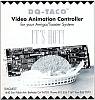
Hersteller Diaquest, USA | Datum 1991 | Amiga A2000, A3000, A4000 | Schnittstelle ISA, serieller Port |
Nur englische Beschreibung vorhanden:
- single frame controller
- controls up to two RS-422 equipped VTRs at once
- offers more than 60 commands to control the VTR
- the card is controlled via the serial port - a cable is included for the A2000 internal serial port, an adaptor is required for the A3000 and A4000
- can use any communications program that uses the serial port
- designed with the Video Toaster in mind - the bundled software is prepared for use with LightWave 3D only
- using other hardware and software is also possible, as long as the user renders his images onto disk, uses a display utility with his graphics card, and sends the appropriate DQ-Taco command to the serial port
Werbung (US)
1992-03
Hersteller Feral Industries, USA | Amiga A2000, A3000, A4000 | Schnittstelle ISA |
Nur englische Beschreibung vorhanden:
- time base corrector and digital video effects
- produces 6 MHz bandwith with digital comb filtering and line and pixel interpolation
- compresses video images vertically and horizontally then positions them anywhere on the screen - user selectable beginning and ending size, position and duration
- composite, Y/C and genlock inputs
- composite, Y/C and alpha outputs
- transcodes simultaneously to both outputs from either input
- genlock with SC and H phase controls
- field 1 and field 2 freeze and variable strobe
- memorised proc amp controls
- PAL and NTSC compatible
- controlled through the serial port or by the optional remote control

Vorderseite

Rückseite
Hersteller Software Results Enterprises, USA | Datum 1994 | Amiga A2000, A3000, A4000 | Schnittstelle Zorro II, ISA | Autoconfig-ID 2150 / 1 |
- ermöglicht den Einsatz preisgünstiger ISA-Karten im Amiga
- unterstützt sämtliche PC-Interrupts und I/O-Adressen
- unterstützt keine ISA-DMA-Übertragungen (u.a. benötigt für PC-Diskettenlaufwerke)
- alle Address- und Datenleitungen zum PC-Bus sind gepuffert, um die Busleitungen des Amigas zu entlasten
- Treiber unterstützt:
- 4 serielle Ports / Modem-Karten (ibmser.device)
- 3 parallele Ports - unidirektional (ibmprint.device)
- 2 IDE-/RLL-/MFM-Festplatten (ibmIDE.device)
- 1 NE1000- / NE2000-Netzwerkkarte (8 bzw. 16 Bit) - SANA-II kompatibel (NE1000.device, NE2000.device)
- wird von OpenBSD unterstützt

Vorderseite

Rückseite

Vorderseite
- GoldenGate2plus-12.dms
driver disk v1.2 (ibmide.device 1.0, ibmprint.device v2.02, ibmser.device v2.07, network drivers v37.7
319 kB - GoldenGate2plus-Network-3724.lha
SANA2 network drivers v37.24
199 kB - GoldenGate2plus-NetworkND-3724.lha
SANA2 network drivers v37.24 (non-debug versions, faster)
47 kB - GoldenGate2plus-ibmIDE-20beta.lha
ibmide.device v2.0beta (supports HDToolbox, does not work with all IDE drives) and RDBmounter v2.0beta
13 kB
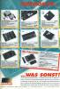
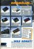
Hersteller Vortex, Deutschland | Datum 1992 / 1993 / 1994 | Amiga A2000, A3000, A4000 | Schnittstelle Zorro II, ISA | Autoconfig-ID 8215 / 7,8,9 |
- Emulation des IBM AT
- CPU: 80386SX @ 25 MHz, 80486SLC @ 25 MHz oder 80486SLC2 @ 50 MHz (32 Bit intern, 16 Bit breiter externer Datenbus, 1 kB interner Cache, 2.4 mal schneller als ein 386SX)
- FPU: optional
- optionales HD-/ED-Controllerkit (82077AA-Chip) für Disketten mit 1.2/1.44/2.88 MB - max. 3 Laufwerke (2 intern, 1 extern)
- interner Anschluß für ein Diskettenlaufwerk sowie externer DB25-Port für externe Laufwerke (HD-Kit wird benötigt)
- kann Amiga-Diskettenlaufwerke als PC-Laufwerk mit 360 oder 720 kB Kapazität benutzen
- DB9-Anschluß für den optionalen Umschalter Monitor Master
- eingebaute IDE-Schnittstelle
- Festplatten werden über MS-DOS-formatierte Amiga-Partitionen oder Hardfiles emuliert
- 27 verschiedene emulierte Bildschirmmodi (z.B. CGA mit vier Farben, Monochrom-VGA, 8-farbiges VGA im Textmodus)
- emulierte Bildschirmmodi können mit 15 kHz Zeilenfrequenz dargestellt werden
- durch Einstecken einer ISA-Grafikkarte wird die emulierte Grafik automatisch abgeschaltetet
- 512 kB auf der Karte + vier SIMM-Steckplätze mit maximal 16 MB
- 2 bzw. 4 MB des 'Golden Gate'-RAMs können vom Amiga benutzt werden
- 50% des Amiga-RAMs (Chip-, Fast- oder public RAM) können für den Emulator genutzt werden
- verfügt über Echtzeituhr, Speaker und CMOS-RAM
- im Servermodus kann der Amiga das RAM und die Laufwerke der Golden Gate direkt ansprechen
- die Amiga-Maus wird als serielle Microsoft-Maus emuliert
- die serielle Schnittstelle des Amiga kann von der Golden Gate als COM1 oder COM2 genutzt werden, der Parallelport als LPT1 oder LPT2
- für den Einsatz in einem A2000 wird ein Adapter benötigt (verbindet zwei Pins des 68000 über einen Kondensator)
- im A3000 wird mindestens ein Buster Rev. 07 benötigt
- Jumper-Settings
| J1 | gesetzt | reserviert |
| J4 | open | reserviert |
| J5 | open | reserviert |
| J8 | gesetzt | Speaker aktiviert |
| J8 | offen | Speaker deaktiviert |
| J2 | J3 | |
| offen | offen | Option-ROM deaktiviert |
| gesetzt | offen | 2MB für Amiga |
| gesetzt | gesetzt | 4MB für Amiga |

Golden Gate 486SLC2, Vorderseite

Golden Gate 486SLC2, Rückseite

Golden Gate 386SX, Vorderseite

Golden Gate 386SX, Rückseite
- GoldenGate486.dms
install disk (Amiga side)
309 kB - GoldenGate486.zip
install disk (PC side)
36 kB
Werbung (GB)
1993-02
Werbung (DE)
1992-10
Werbung (DE)
1992-11
Werbung (US)
1992-12
Werbung (FR)
1992-12
Hersteller Individual Computers, Deutschland | Datum 2008/2009 | Amiga A1200, A4000, CD32 | Schnittstelle Lisa-Chip |
- Flicker-Fixer
- mit einem maximalen Eingangs-Pixeltakt von 28 MHz können alle Amiga-Modi entflickert werden (mit Ausnahme des A2024-Modus)
- Bildwiederholraten von mindestens 60 Hz für alle Bildschirmmodi (ergibt einen Ausgangspixeltakt von bis zu 71 MHz)
- unterstützt eine Palette von 16.7 Millionen Farben (24 bit)
- unterstützt Interlace- und Progressive-Modi
- Ausgabemodi sind immer im Modus Progressive Scan
- zwei verschiedene Ausgangsmodi können ausgewählt werden:
- Async-Modus: Ausgangspixeltakt entspricht dem 2.5-fachen des Amiga-Taktes
- Vertical-Sync-Modus: exakte Verdoppelung des Amiga-Pixeltaktes (elimiert Tearing-Effekte)
- wird nur auf den Lisa-Chip gesteckt, keine Lötarbeit nötig
- bezieht Spannung und alle Signale von diesem Chip
- Sync-Signale werden aus der Kommunikation zwischen den Chips des AGA-Chipsatzes gewonnen
- 15-pol. VGA-Ausgang (HD15)
- unterstützt Border Blanking
- 16 Megabyte SDRAM
- bei SDRAM sind Lese- und Schreibzugriffe nicht gleichzeitig möglich (Single-Port), deshalb sind diese entkoppelt mit zwei FIFO-Puffern und einem SDRAM-Controller mit einem Takt von 111 MHz
- nur 12 MB des Speichers werden genutzt, 4 MB bleiben frei
- Speicher-Layout entspricht 2048x2048 Pixeln (entspricht maximaler Auflösung)
- Genlock-kompatibel
- kein Durchleitungsmodus (Passthrough) - alle Modi werden entflickert
- FPGA-basiertes Design mit FlashROM
- Rettungsmodus (spezielle Rettungsdiskette nötig) falls ein Firmware-Update schiefgelaufen ist
- geringe Hitzeabstrahlung durch 2.5V-/3.3V-Design (nur der Spannungsregler benötigt noch 5V)
- Einschaltbild mit Timeout - falls wichtige Informationen gezeigt werden (z.B. Guru-Screen, oder Early Startup Menu) wird diese Zeit automatisch reduziert
- kein Treiber nötig, allerdings werden zusätzliche Bildschirm-Modi unterstützt:
- HighGFX (1024×786)
- HD720 (1280×720)
- Indivision AGA 1200
- Aussparungen in der Leiterplatte ermöglichen die Installation von anderen internen A1200-Komponenten wie z.B. IDE-Fix Express oder Lyra 1200 - der Platz wird maximal ausgenutzt, deswegen können sich die Erweiterungen bei bestimmten Board-Revisionen berühren
- Karten der ersten Revision waren anfällig dafür, sich leicht vom Lisa-Chip zu lösen - in späteren Revisionen wurde daher der Lisa-Sockel maschinell nachbearbeitet
- Indivision AGA 4000
- dies ist das Nachfolgedesign zum Indivision AGA 1200 und bietet die selben Merkmale, aber ein anderes Platinenlayout um in A4000D und CD32 zu passen
- zusätzliche 10nF-Kondensatoren für die PLLs
- zwei (anstelle ein) TTL-Treiber für die VGA-Sync-Leitungen
- Prototypkarte besitzt eine weisse, die endgültige Version eine blaue Leiterkarte

Indivision AGA 1200, Vorderseite

Indivision AGA 1200, Rückseite

Indivision AGA 4000 Prototyp, Vorderseite

Indivision AGA 4000 Prototyp, Rückseite
Hersteller Individual Computers, Deutschland | Datum 2012/2013 | Amiga A1200, A4000T, A4000, CD32 | Schnittstelle Lisa-Chip |
- Flicker-Fixer
- alle Amiga-Modi können entflickert werden (mit Ausnahme des A2024-Modus)
- Bildwiederholraten von mindestens 60 Hz für alle Bildschirmmodi (ergibt einen Ausgangspixeltakt von bis zu 71 MHz)
- unterstützt eine Palette von 16.7 Millionen Farben (24 bit)
- unterstützt Interlace- und Progressive-Modi
- Ausgabemodi sind immer im Modus Progressive Scan
- zwei verschiedene Ausgangsmodi können ausgewählt werden:
- Async-Modus: Ausgangspixeltakt entspricht dem 2.5-fachen des Amiga-Taktes
- Vertical-Sync-Modus: exakte Verdoppelung des Amiga-Pixeltaktes (eliminert Tearing-Effekte)
- wird nur auf den Lisa-Chip gesteckt, keine Lötarbeit nötig
- bezieht Spannung und alle Signale von diesem Chip
- Sync-Signale werden aus der Kommunikation zwischen den Chips des AGA-Chipsatzes gewonnen
- DVI-Ausgang (DVI-I)
- unterstützt Border Blanking
- 16 Megabyte SDRAM
- Speicher-Layout entspricht 2048x2048 Pixeln (entspricht maximaler Auflösung)
- Genlock-kompatibel
- kein Durchleitungsmodus (Passthrough) - alle Modi werden entflickert
- FPGA-basiertes Design mit FlashROM
- Rettungsmodus (spezielle Rettungsdiskette nötig) falls ein Firmware-Update schiefgelaufen ist
- geringe Hitzeabstrahlung durch 2.5V-/3.3V-Design (nur der Spannungsregler benötigt noch 5V)
- power-on picture with timeout - that timeout is decreased in case the Amiga screen displays vital information (e.g. Early Startup Menu, Error or Guru screens)
- kein Treiber nötig, allerdings werden zusätzliche Bildschirm-Modi unterstützt:
- HighGFX (1024×786)
- HD720 (1280×720)
- Xtreme (1280×1024)
- SuperPlus (800×600)
- Konfigurationstool zum Flash-Update und zum Einstellen der Bildschirmparameter
- der Lisa-Sockel wurde maschinell nachbearbeitet
- im Vergleich zur Vorgänger-Revision besitzt diese einen schnelleren FPGA, schnelleren Speicher und flexiblere Pixeltakte - die Hauptfeatures bleiben bestehen
- Indivision AGA MK2 1200 / A4000T (2012)
- DVI-Ausgang befindet auf einer kleinen zusätzlichen Platine
- Indivision AGA MK2 4000 / CD32 (2012)
- DVI-Ausgang befindet auf einer kleinen zusätzlichen Platine
- anderes Boardlayout für A4000D und CD32, aber die Technik ist gleich zur Indivision AGA MK2 1200 / A4000T
- Indivision AGA MK2cr 1200 / A4000T (2013)
- kostensparende Version:
- die Komponenten von der zusätzlichen Platine wurden auf die Indivision-Platine integriert
- DVI-I-Ausgang (vergossener Stecker) wird direkt angeschlossen
- passt in den A4000T nicht ohne Modifikation: der Anschluss für den DVI-Ausgang stößt an den Elko CE164C auf der Hautplatine an - dieser muss durch einen niedrigeren Keramikkondensator ersetzt werden
- die Pins für den Lisa-Sockel sind mit einem speziell angefertigten Werkzeug hergestellt, damit sitzt die Indivision-Platine fester
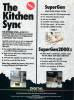
Hersteller Digital Creations / Progressive Image, USA | Datum 1991 | Amiga A2000, A3000, A4000 | Schnittstelle ISA |
Nur englische Beschreibung vorhanden:
- time base corrector & sync generator
- two infinite window time base correctors on one card
- completely synchronizes two independent video sources
- multiple Kitchen Syncs can be used together for even more channels
- completely accurate sync generator - totally regenerates all sync and blanking signals
- built in proc amp
- external LCD control panel
- S-VHS and Hi8 compatible inputs - can use composite or S-Video into either channel
- advanced sync output
- S-VHS output option
- genlock option
- jitter free freeze frame, field1 or field2
- variable rate strobe
- external contact closure interface for freeze
- three user presets and one factory setting stored internally

Vorderseite
Werbung (US)
1991-07
Werbung (US)
1993-04
Werbung (US)
1993-09
Werbung (US)
1993-11
Werbung (US)
1994-07
Hersteller Magni Systems, USA | Datum 1988 | Amiga A2000, A3000, A4000 | Schnittstelle ISA, Video-Steckplatz |
Nur englische Beschreibung vorhanden:
- genlockable video graphics encoder
- 4004 NTSC, 4005 PAL
- extremely clean and reliable, broadcast quality device for overlaying titles and graphics with the Amiga
- built-in system timing and controlled signal edges assure excellent performance upstream or downstream of the switcher
- four genlocking modes
- sync and burst lock - output video is referenced to the incoming video
- burst lock - for editing systems that need to maintain correct SC/H phasing
- sync lock - for laying computer graphics over a monochrome signal
- internal reference
- black burst generator
- video mixer - capable of manual, automatic or software controlled transitions
- adjustable fade rate, fade level, key level, key normal / invert, quick fade and auto fade to video or to graphics
- consists of two cards, connected to each other with ribbon cables
- Video Interface - goes to the video slot, the remote control box attaches to its DB25 connector
- Encoder / Genlock - installs into an XT slot (takes power only), the breakout cable with four BNC connectors attaches to its DB9 port
- uses the 4 bit digital signals of the video slot instead of the analog RGB signal other genlocks use - the board recreates the RGB signal on its own ensuring to meet all broadcast standards
- requires modification for A3000 compatibility
- optional Magni 4010 remote control box
- inputs / outputs
- Magni 4004 & 4005:
- Composite Video In
- Composite Video Out
- External Key In
- Key Out / Preview Out / Black Burst Out - the selection is made by jumpers
- Magni 4004S:
- Composite Video In
- S-VHS Out (Amiga graphics only)
- Composite Video Out (Amiga + video)
- External Key In

Magni 4005 Video-Karte, Vorderseite

Magni 4005 Video-Karte, Rückseite

Magni 4005 Encoder-Karte, Vorderseite

Magni 4005 Encoder-Karte, Rückseite

Magni 4004 Video-Karte, Vorderseite

Magni 4004 Encoder-Karte, Vorderseite
- Magni4004.pdf
Operator's Manual
1722 kB
- Magni4004.dms
demo disk showing test patterns
116 kB
Hersteller Sang Computersysteme, Deutschland | Datum 1988,1989 | Amiga A2000 | Schnittstelle Zorro II, ISA |
Nur englische Beschreibung vorhanden:
- interface for transputer cards
- connects to a Zorro II slot
- the transputer cards connect to XT slots
- the interface card connects to the transputers externally
- any number of transputer cards can be attached together
- Helios operating system
- MegaLink 01 (1988)
- four Inmos T414 or T800 processors
- each processor has its own memory - 1 or 4 MB RAM in four 30 pin SIMM sockets
- MegaLink 02 (1989)
- one Inmos T424 or T800 @ 20 / 25 / 30 MHz processor
- 1, 2, 4 or 8 MB RAM with 16 ZIP chips
- Inmos G300 programmable RAMDAC
- 110 MHz video clock
- 1 or 2 MB dual ported VRAM
- resolutions from 512×512 to 8192×8192 (the latter with multiple boards)
- video data may not only be written by the local transputer but by other ones too - parallel image processing
- port for connecting a framegrabber or a U-Matic Video Machine
- distributed overseas by Digital Animation Productions as Video Graphics Transputer
- MegaLink 03 (1989)
- one Inmos T425 or T800 processor
- up to 32 MB RAM
- DMA interface
- compatible and cascadable with all MegaLink boards and other Inmos B004/B008 compatible systems
Hersteller Digital Processing Systems, Kanada | Datum 1994 & 1995 | Amiga A2000, A3000, A4000 | Schnittstelle ISA |
Nur englische Beschreibung vorhanden:
- video synchronizer
- unlike infinite window TBCs, the MicroSync features four-field composite processing - this eliminates the need to separate the incoming video signal into chrominance and luminance components
- delivers transparent, stable video, free of bandwidth limitations or comb filter artifacts
- any direct color or monochrome signal can be connected, such as the output of a satellite receiver or camera
- cannot process non time base corrected heterodyne signals, such as those from U-Matic or VHS machines - for those sources, the MicroSync can be mixed with the Personal TBC 4 Plus wideband TBC card
- selectable frame and field freeze, variable strobe, digitally controlled proc amp settings, selectable hot-switch modes, dual clamp speeds, genlock loop, RS-232 serial control
- four-field, two-field and hot frame modes, automatic bypass upon loss of power, nonvolatile proc amp memory, adjustable vertical blanking width
- controlled via the serial port
- MicroSync-20a.lha
MicroSync controller v2.0a
28 kB
Hersteller ArMax, Deutschland | Datum 1993 | Amiga A2000, A3000, A4000 | Schnittstelle Zorro II, ISA | Autoconfig-ID 2181 / 0 |
- im Prinzip eine ISA-Zorro-Brückenkarte, ähnlich wie die GoldenGate 2+
- eine Standard-Grafikkarte für den PC belegt einen zweiten ISA-Steckplatz
- Grafikprozessor: Tseng Labs ET4000AX
- 1 MB RAM
- 1280×1024 87 Hz interlaced, maximal 16 Farben aus einer 18-Bit-Palette (262144)
- 1152×900 60 Hz, maximal 256 Farben aus 18Bit
- 1120×832 65 Hz, maximal 256 Farben aus 18Bit
- 1024×768 70 Hz, maximal 256 Farben aus 18Bit
- 800×600 72 Hz, maximal 32768 Farben aus einer 15-Bit-Palette (32768)
- 640×480 81 Hz, maximal 32768 Farben aus 15Bit
- Ausgang: VGA (DB15)
- Treiber: Picasso96 und kartenspezifische
- wird von NetBSD und OpenBSD unterstützt
- RTG-Grafikkarte
- sechs vordefinierte Bildschirmmodi
- Bemerkungen
Hersteller Prime Image, USA | Datum 1992 | Amiga A2000, A3000, A4000 | Schnittstelle ISA |
Nur englische Beschreibung vorhanden:
- time base corrector
- composite, Y/C and genlock inputs
- composite and Y/C outputs
- transcodes simultaneously to both outputs from either input
- fully digital operation, no adjustments needed
- stable freeze frame
- variable rate strobe
- provides timing into Switcher (Video Toaster)
- vertical colour advance - 1, 2 or 3 lines
- horizontal chroma / luma adjust
- four event memory presets per board
- controlled by the host computer terminal (via serial port) or the optional remote control unit:
- proc amp video output adjustments, including video level (contrast), chroma level (stauration), hue (tint), setup (brightness)
- field or frame freeze and strobe
- horizontal and subcarrier system timing, horizontal position, Y/C delay
- input select and signal enhancement
- NTSC and PAL-M (525 lines) or PAL (625 lines) versions
- 5.5 MHz Y/C bandwidth
- 58 dB S/N ratio

Vorderseite
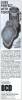
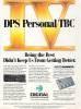
Hersteller Digital Processing Systems, Kanada | Datum 1991 | Amiga A2000, A3000, A4000 | Schnittstelle ISA |
- Korrektur der Zeitbasis des ganzen Frames ('infinite window')
- Ein-/Ausgänge: Composite und S-VHS (alle Cinch)
- Cinch-BNC-Adapter wude mitgeliefert
- keine Möglichkeit zum Einfrieren eines Frames oder zur Steuerung der 'Proc Amp'-Parameter
- die einzige Steuerungsmöglichkeit ist ein Schalter zum Anpassen der Phasentimings
- nur NTSC
- Time Base Corrector (TBC)

Vorderseite
Werbung (US)
1991-04
Hersteller Digital Processing Systems, Kanada | Datum 1992 | Amiga A2000, A3000, A4000 | Schnittstelle ISA |
- VT-2000 NTSC, VT-3000 PAL
- Korrektur der Zeitbasis des ganzen Frames ('infinite window')
- Ein-/Ausgänge: Composite und S-VHS
- Video-Eingang für Referenzsignal, erweiterter Sync-Ausgang
- genlock-fähig
- ideal für A/B-Roll-Editing
- Softwaresteuerung des Verstärkers, des Timings und der Farbbalance
- Bandbreite: 3.5 MHz (PAL) bzw. 5.5 MHz (NTSC)
- Signal-Rausch-Abstand: 58 dB
- wird gesteuert über den seriellen Port
- Time Base Corrector (TBC)

Vorderseite
- PersonalTBC2-30.lha
TBC II controller v3.0
130 kB

Werbung (US)
1991-12
Werbung (US)
1992-03
Hersteller Digital Processing Systems, Kanada | Datum 1993 | Amiga A2000, A3000, A4000 | Schnittstelle ISA |
- Korrektur der Zeitbasis von 3 Fields ('infinite window')
- Ein-/Ausgänge: Composite und S-VHS
- Video-Eingang für Referenzsignal, erweiterter Sync-Ausgang
- kann genutzt werden, um beinahe jeden Videorecorder, Laserdisc-Player oder Camcorder mit Umschaltern oder Computer-Videosystemen (z.B. Video Toaster) zu verbinden
- Spezialeffekte: sehr stabiles Einfrieren eines Fields oder Frames, variables Strobe, Monochrom-Darstellung
- Softwaresteuerung des Video-Verstärkers, des System-Timings und der Farbbalance
- Bandbreite: 2.5 MHz (Composite), 5.5 MHz (S-VHS)
- Signal-Rausch-Abstand: 58 dB
- nur NTSC
- wird gesteuert über den seriellen Port
- Time Base Corrector (TBC)

Vorderseite
- PersonalTBC3-20.dms
install disk
Personal TBC-III program v2.0
50 kB - PersonalTBC3-20.lha
TBC III controller v2.0
44 kB
Werbung (US)
1992-10
Hersteller Digital Processing Systems, Kanada | Datum 1994 | Amiga A2000, A3000, A4000 | Schnittstelle ISA |
- component digital 4:2:2 processing
- infinite window (3 fields) correction
- composite, wideband S-VHS, reference video and GPI freeze trigger inputs
- composite, wideband S-VHS and advanced sync outputs
- full proc amp and colour balance, horizontal and vertical Y/C delay, freeze field, freeze frame, variable strobe, film-mode strobe, GPI freeze, memory store / recall, genlock timing
- when combined with the Personal Animation Recorder:
- the TBC IV functions as a live video capture board for the DR-2150 card
- connects to the PAR with a 50 pin ribbon cable via the Component Video Exchange (CVE) bus
- with this combination live video can be recorded on the animator's hard drive
- NTSC only
- 2.5 MHz (VT-2600) or 5.5 MHz (VT-2600WB) composite bandwidth, 5.5 MHz S-VHS bandwidth
- 58 dB S/N ratio
- optional DC-2600 Wideband Comb Filter Decoder daughtercard:
- 3-line adaptive comb filter decoder boosts the composite bandwidth from 2.5 MHz to 5.5 MHz, making it suitable for use with U-Matic-SP VCRs
- included with the TBC 4 Plus
- controlled via the serial port
- time base corrector

Vorderseite
- PersonalTBC4-22.dms
install disk
Personal TBC-IV program v2.2
50 kB - PersonalTBC4-30.lha
TBC IV controller v3.0
32 kB
Werbung (US)
1993-09
Hersteller Digital Processing Systems, Kanada | Amiga A2000, A3000, A4000 | Schnittstelle ISA |
Nur englische Beschreibung vorhanden:
- VM-2000 NTSC, VM-3000 PAL
- the world's first waveform monitor and vectorscope for desktop video
- produces a digitally synthesized waveform monitor and vectorscope display that can be superimposed onto any video signal
- provides a buffered video output, a superimposed (software controlled) video output, a full-time waveform / vector video output
- when combined with the Personal TBC II, III or IV, the V-Scope provides a fully integrated video processing, manipulating and monitoring environment
- test signals: SMPTE colour bars, E/A bars, full field bars, bars / luma bars, bars / red, bars / reverse bars, bars / modulated timing pulses, luma only bars, multiburst 60 and 100 IRE, line sweep 0-4.2 MHz, chroma sweep 0-500 kHz, pulse and bars with window, convergence grid, black field 7.5 IRE, gray field 50 IRE, white field 100 IRE, red field, modulated 5 step, luma 5 step, modulated ramp, luma ramp, demodulator alignment ramp, FCC composite, NTC7 combination, multi pulse, sin (x)/x, matrix
- software control
- controlled via the serial port
- selection of waveform / vector modes
- enable / disable superimpose mode
- integrated control with Personal TBC III
- vector scope
- displays colour component signals
- graticule targets for colour bars test signal
- linear quadrature decoder
- waveform monitor
- displays video signal level
- graticule calibrated in IRE/m volt scales
- 2H and 1H display modes
- switchable low pass filter
- DIP switch settings
| 1 ON OFF | - baud rate - 31250 bps (Amiga built-in serial port) - 9600 bps (IBM PC or A2232) |
| 2 ON OFF ON OFF ON OFF ON OFF |
3 ON ON OFF OFF ON ON OFF OFF |
4 ON ON ON ON OFF OFF OFF OFF |
- power up mode - full screen waveform (1-H) - full screen waveform (2-H) - full screen vector - waveform (1-H) / vector overlay - waveform (2-H) / vector overlay - waveform / vector split screen - waveform (LPF) / vector split screen - full screen waveform (LPF) |

Vorderseite

Vorderseite
- PersonalVScope-20.lha
V-Scope controller v2.0
95 kB
Werbung (US)
1992-04
Werbung (US)
1992-05
Werbung (US)
1992-10
Hersteller Digital Processing Systems, Kanada | Amiga A2000, A3000, A4000 | Schnittstelle Zorro II, ISA |
- verteilt einen Video-Eingang auf 4 Ziele (mit 75 Ohm abgeschlossen)
- der Video-Eingang ist Wechselspannungs-gekoppelt und bietet eine abschaltbare Terminierung (75 Ohm)
- ideal für Bandvervielfältigung, Mehrmonitorsysteme im Verkaufsbereich, Verteilung von Genlock-Referenzsignalen oder zur Isolation mehrerer Videosysteme voneinander (Vermeidung von Schleifen)
- Video-Verteilungs-Verstärker

Vorderseite

Vorderseite
Hersteller Digital Processing Systems, Kanada | Amiga A2000, A3000, A4000 | Schnittstelle ISA |
Nur englische Beschreibung vorhanden:
- composite video routing switcher
- provides video monitor switching for multiple MicroSync or Personal TBC IV cards
- contains a 4×1 and an 8×1 switching matrix
- the 4×1 matrix inputs are connected to BNC connectors located on the back of the card
- inputs to the 8×1 matrix originate from the card edge (ISA) connector, so this switching matrix is unused in Amiga systems (it is limited to use with the DPS ES-2000 rackmount expansion system)
- the outputs of either matrix can be routed to a BNC connector or to the card edge connector
- can be controlled via the serial port with the control software of the Personal TBC or MicroSync cards

Vorderseite
Hersteller Prime Image, USA | Datum 1993 | Amiga A2000, A3000, A4000 | Schnittstelle ISA |
Nur englische Beschreibung vorhanden:
- standards converter & time base corrector
- accepts synchronous or non-synchronous inputs
- mode selection and conversion of all world television standards: NTSC, PAL, PAL-M, SECAM (input only), PAL-N, NTSC 4.43
- converts the Video Toaster NTSC input and output to PAL
- composite, Y/C and genlock inputs
- composite and Y/C outputs
- transcodes simultaneously to both outputs from either input
- automatic gain control
- 3 levels detail enhance
- controlled by the host computer terminal (via serial port) or the optional remote control unit:
- proc amp video output adjustments, including video level (contrast), chroma level (stauration), hue (tint), setup (brightness)
- field or frame freeze and strobe
- horizontal and subcarrier system timing, horizontal position, Y/C delay
- input select and signal enhancement
- non-blurring / non averaging interpolation system
- CCIR-601 4:2:2 processing
- 5.5 MHz Y/C bandwidth
- 58 dB S/N ratio
- optional 3-way adaptive comb filter
- separates the composite signal into its two components, Y (luminance) and C (chrominance) while maintaining bandwidth
- reduces the differential phase, differential gain and K-factor specifications while ensuring the frequency response stays flat out to 5.5 MHz
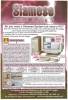
Hersteller HiQ, UK | Datum 1996 | Amiga jeder Amiga | Schnittstelle ISA |
- Amiga kann auf PC-Geräte (Festplatten, CD-ROM, Netzwerklaufwerke, Drucker) zugreifen
- Amiga und PC können eine Maus und, mit optionaler Video-Umschalterkarte, einen Monitor gemeinsam nutzen
- Installation in einen PC-ISA-Steckplatz
- zwei VGA-Eingänge (DB15) - jeweils einer für Amiga und PC
- ein VGA-Ausgang (DB15) zum Anschluss an gemeinsam genutzten Monitor
- gemeinsam nutzbares Text-Clipboard
- per Voreinstellung wird jegliche Kommunikation über ein Nullmodemkabel abgewickelt
- SCSI-Netzwerkunterstützung - beschleunigt Datenübertragung zwischen Amiga und PC
- unterstützte Amiga-SCSI-Controller: integrierter Controller des A3000(T)/A4000T, A4091, Oktagon, Surf Squirrel, DKB Ferret
- unterstützte PC-SCSI-Controller: Adaptec 1505/1541/2940, NCR 810
- TCP/IP-Netzwerkunterstützung - Datenübertragung über Ethernet
- RTG-Unterstützung - Amiga-Bildschirme können auf der PC-Grafikkarte mit max. 256 Farben dargestellt werden
- RTG funktioniert mit serieller oder TCP/IP-Verbindung
- RTG mit max. 65536 Farben
- RTG funktioniert nur mit TCP/IP-Verbindung
- Beschleunigung von Video-Wiedergabe - Dekodierung und Darstellung geschieht über PC-Grafikkarte
- integriert Amiga und PC
- Siamese-Software v1.5
- Siamese-Software v2.1
- Siamese-Software v2.5

Siamese Video-Umschalter, Vorderseite
Werbung (GB)
1996-12
Werbung (GB)
1997-03
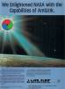
Hersteller TrueVision, USA | Datum 1990 | Amiga A2000, A3000, A4000 | Schnittstelle ISA |
Nur englische Beschreibung vorhanden:
- framebuffer
- while strictly PC boards, some Amiga applications directly support them as framebuffers through a BridgeBoard with Janus software
- Caligari Broadcast has native support for the Targa boards (including saving in Targa format, automatic transferring through the BridgeBoard and loading the image into the Targa framebuffer)
- Sculpt renders directly through the Sculpt-Direct and Targa-Direct (TGALink) modules of Active Circuits' ImageLink software
- the various Targa, Targa+ and ATVista boards can do much more than displaying 24 bit images in their framebuffer, but those features (capture, live overlay, keying, etc.) are not utilized by Amiga applications
Hersteller PreVue Technologies, USA | Amiga A2000, A3000, A4000 | Schnittstelle ISA |
Nur englische Beschreibung vorhanden:
- sync generator
- designed to advance the sync reference signal for the Video Toaster so that the Toaster Program output signal will be in time with the sync reference signal
- the sync reference can be either a standard Black Burst reference signal or any other stable test signal
- separate subcarrier and horizontal adjustments are provided to establish SC/H phasing
- a reference signal must be supplied to the Toast Timer - it is not designed to be used as a stand alone Black Burst generator and will not provide a proper signal without a reference input
- includes a jumper that allows for extended range for use with other Video Toaster accessories such as Y/C interface boards
- when the Toast Timer is used in conjunction with 1 or 2 BreadBoards feeding another downstream switcher, it is recommended that a Program output feed from one of the BreadBoards be connected as the Video Toaster input to the downstream switcher

Vorderseite

Vorderseite
Hersteller Y/C Plus Inc., USA | Datum 1996 | Amiga A2000, A3000, A4000 | Schnittstelle ISA |
- kalibriert den Oszillator auf dem Video Toaster
- hilft bei der Vermeidung der Fehlermeldungen "Toaster Not Responding", "Toaster Will Not Genlock" oder "Toaster Will Not Auto Hue"
- Anschluss an JP6 des Video Toasters über ein Flachbandkabel
- überprüft das Computernetzteil, indem es die Spannungen +12V, -12V, +5V, -5V mit LEDs anzeigt
- die Karte wird nicht dauerhaft installiert, sondern nur zur Durchführung der Überprüfung / Kalibrierung
- Video-Toaster-Kalibrierer

Vorderseite