Search Result
35 expansions found
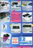
Manufacturer Roßmöller, Germany | Date 1990 | Amiga A2000, A3000, A4000 | Interface ISA |
- IBM AT emulation
- 386 upgrade expansion for the A2088XT
- connects to a free ISA XT slot
- a ribbon cable connects the 386si and the A2088XT
- the 8088 has to be replaced from the A2088XT to the 386si
- 80386 SX @ 16 MHz
- 16 kB static cache RAM
- sockets for up to 8 MB RAM
- not fully compatible with Janus software
Advert (DE)
1990-05
Advert (DE)
1990-07
Advert (DE)
1990-09
Manufacturer Commodore, USA | Date 1990 | Amiga A2000, A3000, A4000 | Interface Zorro II, ISA |
- IBM XT emulation
- NEC V20 @ 4.77 / 7.15 / 9.54 MHz (PLCC)
- the different clock speeds are switchable by software (Ctrl-S, Ctrl-T, Ctrl-D)
- 640 kB RAM
- 16 kB XT compatible BIOS
- no floppy drive supplied - it uses the built in 3.5" Amiga disk drive
- the drive can either shared between the Amiga and PC, either assigned exclusively to one of them
- can use any other Amiga floppy drives too: internal or external, DD or HD, 3.5" or 5.25"
- parallel interface and mouse are emulated by the Amiga
- piezo beeper

front side

back side
- CBM-PCInstall-334.dms
install disk v1.02
janus.library v33.4 (11.09.1989)
328 kB - CBM-PCJanus.zip
PC Software
99 kB
Manufacturer Commodore, USA | Date 1986 | Amiga A2000, A3000, A4000 | Interface Zorro II, ISA | Autoconfig ID 513 / 1 |
- IBM XT emulation
- 8088 @ 4.77 MHz
- optional 8087 FPU
- 512 kB RAM
- 16 kB XT compatible BIOS
- 360 kB 5.25" floppy drive supplied
- 720 kB 3.5" - uses external Amiga floppy drives on the external connector
- CGA 640x200x2 or 320x200x4 modes selectable with jumpers
- can use Amiga parallel ports
- could be upgraded to 386 with the Roßmöller 386si

front side

back side
- A2088-A2286.pdf
user's guide
38.0 MB - A2088XT.pdf
user manual (german) + addendum
734 kB
- A2088Turbo.lha
speedup modification
7 kB - CBM-AmigaJanus21-3683.dms
install disk v2.1
janus.library v36.83 (21.8.91)
280 kB - CBM-PCInstall-322.dms
install disk
janus.library v32.2 (25.04.1986)
182 kB - CBM-PCInstall-331.dms
install disk
janus.library v33.1b5 (25.10.1988)
324 kB - CBM-PCInstall-334.dms
install disk v1.02
janus.library v33.4 (11.09.1989)
328 kB - CBM-PCJanus.zip
PC Software
99 kB
Manufacturer Commodore, USA | Date 1989 | Amiga A2000, A3000, A4000 | Interface Zorro II, ISA | Autoconfig ID 513 / 2 |
- IBM AT emulation
- 80286 @ 8 MHz
- optional 80287 FPU
- 1 MB RAM
- 16 kB AT compatible BIOS
- battery connector to store BIOS setup
- 1.2 MB 5.25" floppy drive supplied
- 1.44 MB 3.5" supported
- CGA 640x200x2 or 320x200x4 modes selectable with jumpers
- can use Amiga parallel ports

Main board, front side

Daughterboard, front side

Main board, back side

Daughterboard, back side
- A2088-A2286.pdf
user's guide
38.0 MB
- CBM-AmigaJanus21-3683.dms
install disk v2.1
janus.library v36.83 (21.8.91)
280 kB - CBM-PCInstall-322.dms
install disk
janus.library v32.2 (25.04.1986)
182 kB - CBM-PCInstall-331.dms
install disk
janus.library v33.1b5 (25.10.1988)
324 kB - CBM-PCInstall-334.dms
install disk v1.02
janus.library v33.4 (11.09.1989)
328 kB - CBM-PCJanus.zip
PC Software
99 kB
Manufacturer Commodore, USA | Date 1991 | Amiga A2000, A3000, A4000 | Interface Zorro II, ISA | Autoconfig ID 513 / 103514 / 103 |
- IBM AT emulation
- 80386 SX @ 16 / 20 / 25 MHz (32 bit internally, 16 bit external bus)
- optional 80387 FPU
- sixteen ZIP sockets accept up to 8 MB RAM
- 1 MB factory installed
- supports 256k×4 or 1M×4 page mode ZIPs, 80-120 ns or faster
- accepts ZIPs in groups of four
- 64 kB AT compatible BIOS
- upgrading the BIOS and fitting a ZIP to SIMM converter makes possible to use 16 MB RAM
- 128 kB dual-port RAM for data exchange between the BridgeBoard and the Amiga
- can use a PC hard disk (with additional ISA controller), virtual drives on Amiga partitions (hardfiles), you can even have an Amiga partition on the PC hard drive
- PC floppy drives can be used in an internal bay, Amiga floppy drives can be used as PC only or shared, external Amiga drives can be connected directly to DB23 floppy connector of the BridgeBoard
- only two floppy drives are accessible by the BridgeBoard
- the Amiga supports MDA (monochrome) and CGA modes through the native display (CGA 640x200x2 or 320x200x4 modes) - you can toggle between Amiga and PC screens
- with an ISA VGA board a separate monitor is needed
- the card uses the Amiga's serial or parallel ports for printing
- for modems it can only use an internal ISA modem or serial card
- PC beeper on board
- much slower than a PC with the same processor
- card occupies 512kB in the Zorro II address space - when installed, only 7.5 MB of the address space is left for other expansion cards

front side

back side

front side
- CBM-AmigaJanus21-3683.dms
install disk v2.1
janus.library v36.83 (21.8.91)
280 kB - CBM-PCJanus.zip
PC Software
99 kB
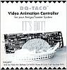
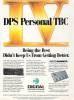
Manufacturer Digital Processing Systems, Canada | Date 1994 | Amiga A2000, A3000, A4000 | Interface ISA |
- realtime digitizer
- realtime capture card for the Personal Animation Recorder DR-3150
- PAL only
- full proc amp controls, freeze frame and freeze field
- connects to the PAR with a 50 pin ribbon cable via the Component Video Exchange (CVE) bus
- composite (BNC), S-VHS, component (3 BNC) inputs

front side
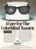
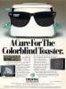
Manufacturer RGB Computer and Video, USA | Date 1991 / 1992 | Amiga A2000, A3000, A4000 | Interface ISA |
- editing controller
- controls the Video Toaster switcher and up to three professional VCRs on a V-LAN network
- can control other switchers via RS-422 or general purpose interface (GPI) triggers
- the V-LAN Universal Control Network is simply an RS-232 protocol adapter that uses device specific software drivers allowing control of VTRs or other devices via a 9 pin RS-422 serial connection
- controls the timing of all audio and video special effects (chroma effects, character generator, keyer, etc.)
- automatic assembly of the edit decision list (EDL)
- supports EDLs from other editing systems in the standard CMX format
- zero frame accuracy
- interfaces through Arexx commands with the Toaster
- there are many versions of the AmiLink hardware (Pro, CI, CIP), the main difference between them is the number of V-LAN transmitters/receivers
- VM-T (V-Lan master controller, 5 BNC) + VM-TRR (three video deck controllers, 2 BNC, 3 DB9)
- VM-T (V-Lan master controller, 5 BNC) + VM-TR (two video deck controllers, 2 BNC, 2 DB9)
- VM-TRR (V-Lan master controller + two video deck controllers, 5 BNC, 2 DB9)
- the master controller communicates with the Amiga through the Amiga serial port
- the software is protected by a parallel port dongle
 front side")
VM-T (master controller), front side
 front side")
VM-TR (master controller + video deck controller), front side
 front side")
VM-TRR (master controller + 2 video deck controllers), front side
Advert (US)
1992-04
Advert (US)
1992-10
Manufacturer Spirit Technology, USA | Date 1990 | Amiga A2000, A3000, A4000 | Interface Zorro II, ISA | Autoconfig ID 2034 / 5 |
- allows using of inexpensive 8 and 16 bit ISA cards in the Amiga
- supplied with basic drivers for hard drive controller and A/D converter cards
- the user has to write his own drivers for his other ISA cards with the help of the included AX-S Resource Library and sample driver source code
Manufacturer BCD Associates, USA | Date 1991 | Amiga A2000, A3000, A4000 | Interface Zorro II, ISA, serial port |
- single frame controller
- although the card has both a Zorro and an ISA connector, they are only used to obtain power, it's enough to connect one of them
- the card is controlled via the serial port - a cable is included for the A2000 internal serial port, an adaptor is required for the A3000 and A4000
- RS-422 control of broadcast / industrial machines
- RS-232 control of VCRs and laser disc recorders
- SMPTE timecode read and generation
- GPI trigger for external devices
- to control the Video Toaster an optional cable is required which connects the GPI trigger connector to the 2nd mouse/joystick port
- the card does not hog the serial port, modems or other serial devices can be used while it's installed

front side
Advert (US)
1992-03
Manufacturer PreVue Technologies, USA | Amiga A2000, A3000, A4000 | Interface ISA |
- delay distribution amplifier
- provides buffered input video in time with Toaster Program output video
- Key signal access to provide independent feeds of Key signals for use in downstream video equipment
- provides direct support for InnoVision's Montage and AlphaPaint programs, exporting linear key (alpha) channel signals
- extra Program/Preview buffers for driving monitors, VTRs, and other equipment
- five video buffer amplifiers, three with delay lines
- the buffers are strappable between Program output, Preview output, Inputs 1-4, Key source signal, and Key Insert video
- the board cables into the Video Toaster feature connectors, it uses none of the six external BNCs
- the delay lines can be strapped for a wide range of delay and adjusted for unity gain
- factory set for delayed output of Input 4, Key Insert, and Key Source - can be configured with soldered straps
- all delay channels (outputs A, B, and C) are factory aligned for unity gain and a delay of 440 ns, the typical delay of a Video Toaster
- outputs D and E have no delay lines and are intended as additional Program and Preview outputs
- output D is always a Program output, exactly the same as the Video Toaster's Program output, though with a slight delay (~20 ns) due to the additional circuitry
- output E can be easily jumpered for either Program or Preview out
- outputs D and E do have overall gain adjustments located at the top edge of the BreadBoard
- the three delay channels (A, B, C) are capable of delaying any of seven signals: Toaster Inputs 1 through 4, internal Toaster Key Source (the "alpha" channel), internal Toaster Key Insert, and Toaster Preview out
- the Key Insert signal is the direct output of one of the framebuffers, DV1 and DV2 - it is not viewable on a picture monitor as it lacks composite sync, it is only suitable as a key source
- it is possible to install two BreadBoards into one system - the 16 wire ribbon cable has dual connectors on one end to facilitate this, the 10 wire ribbon cable need only connect to the BreadBoard that is strapped for Key Source
- when two BreadBoards are ordered direct from VueTech, one will be set for Inputs 1, 2 and 3 and the other set for Input 4 and the two Key signals
- five "Gain" potentiometers on top of the BreadBoard allow gain adjustment of the output signals
- three "Delay" potentiometers allow fine delay adjustment of the output signals
- High Frequency Compensation - a trimmer is provided on each delay channel to adjust high frequency response
- the chroma level on the Program output of some Video Toasters is approximately 5% low - the BreadBoard may be modified to restore the chroma level to full level on the Toaster Program output of the BreadBoard

front side
Manufacturer Mark Tomlinson, New Zealand | Date 1995 | Amiga A2000, A3000, A4000 | Interface Zorro II, ISA |
- allows using of inexpensive ISA cards on the Amiga
- does not support ISA DMA transfers (which is required for PC floppies)
- SANA-II drivers for NE1000 and NE2000 compatible ISA network cards are supplied
- supported by OpenBSD
- IDE controller
- autoboot ROM (xlide.device)
- supports the RDB standard, but filesystems are not loadable from the RDB
- can use an MFM / RLL 16 bit controller instead of the IDE interface
- serial interface
- two onboard serial ports (xlser.device)
- can be activated by plugging in one or two 8250, 16450 or 16550A UART chips
- DB25 and DB9 connectors
Manufacturer Diaquest, USA | Date 1991 | Amiga A2000, A3000, A4000 | Interface ISA, serial port |
- single frame controller
- controls up to two RS-422 equipped VTRs at once
- offers more than 60 commands to control the VTR
- the card is controlled via the serial port - a cable is included for the A2000 internal serial port, an adaptor is required for the A3000 and A4000
- can use any communications program that uses the serial port
- designed with the Video Toaster in mind - the bundled software is prepared for use with LightWave 3D only
- using other hardware and software is also possible, as long as the user renders his images onto disk, uses a display utility with his graphics card, and sends the appropriate DQ-Taco command to the serial port
Advert (US)
1992-03
Manufacturer Feral Industries, USA | Amiga A2000, A3000, A4000 | Interface ISA |
- time base corrector and digital video effects
- produces 6 MHz bandwith with digital comb filtering and line and pixel interpolation
- compresses video images vertically and horizontally then positions them anywhere on the screen - user selectable beginning and ending size, position and duration
- composite, Y/C and genlock inputs
- composite, Y/C and alpha outputs
- transcodes simultaneously to both outputs from either input
- genlock with SC and H phase controls
- field 1 and field 2 freeze and variable strobe
- memorised proc amp controls
- PAL and NTSC compatible
- controlled through the serial port or by the optional remote control

front side

back side
Manufacturer Software Results Enterprises, USA | Date 1994 | Amiga A2000, A3000, A4000 | Interface Zorro II, ISA | Autoconfig ID 2150 / 1 |
- allows using of inexpensive ISA cards on the Amiga
- supports all the PC interrupts and I/O addresses
- no support for ISA DMA transfers (required for PC floppies)
- all address and data lines to the PC bus are buffered to avoid loading down Amiga bus lines
- driver supports
- 4 serial ports / modem cards (ibmser.device)
- 3 parallel ports - not bi-directional (ibmprint.device)
- 2 IDE / RLL / MFM hard drives (ibmIDE.device)
- 1 NE1000 (8 bit) / NE2000 (16 bit) network card - SANA II compatible (NE1000.device, NE2000.device)
- supported by OpenBSD

front side

back side

front side
- GoldenGate2plus-12.dms
driver disk v1.2 (ibmide.device 1.0, ibmprint.device v2.02, ibmser.device v2.07, network drivers v37.7
319 kB - GoldenGate2plus-Network-3724.lha
SANA2 network drivers v37.24
199 kB - GoldenGate2plus-NetworkND-3724.lha
SANA2 network drivers v37.24 (non-debug versions, faster)
47 kB - GoldenGate2plus-ibmIDE-20beta.lha
ibmide.device v2.0beta (supports HDToolbox, does not work with all IDE drives) and RDBmounter v2.0beta
13 kB
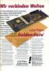
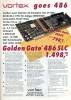
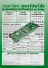
Manufacturer Vortex, Germany | Date 1992 / 1993 / 1994 | Amiga A2000, A3000, A4000 | Interface Zorro II, ISA | Autoconfig ID 8215 / 7,8,9 |
- IBM AT emulation
- 80386SX @ 25 MHz or 80486SLC @ 25 MHz or 80486SLC2 @ 50 MHz (32 bit internal 16 bit external data bus, 1 kB cache inside, 2.4 times faster than 386SX)
- optional FPU
- optional HD/ED (1.2/1.44/2.88 MB) floppy disk controller kit (82077AA chip) for up to 3 drives (2 internal, 1 external)
- internal floppy connector and a DB25 port for external floppies (HD kit required)
- can use Amiga floppy drives as 360 or 720 kB
- DB9 connector for the optional Monitor Master switch
- built in IDE hard disk interface
- hard disks can be emulated either as Amiga partitions formatted to MSDOS or via hardfiles
- 27 different emulated video modes (from 4 color CGA to 2 color VGA or 8 color text only VGA)
- emulated video modes can be displayed in 15 kHz
- inserting an ISA display card automatically disables the video emulation
- 512 kB on board + four SIMM slots max 16 MB, 2 or 4 MB can be used by the Amiga
- 50% of Amiga RAM (this can be split between chip, fast, or public) can be used as RAM for the emulator
- built in realtime clock, speaker, CMOS RAM
- in server mode the Amiga can directly access the RAM and disk drives of the Golden Gate board
- the Amiga mouse is emulated as a serial Microsoft mouse
- the Amiga serial port can be used by the Golden Gate as either COM1 or COM2
- the Amiga parallel port can be used as LPT1 or LPT2 by the Golden Gate
- in A2000 an adapter is required under the 68000 (a simple capacitor is connected between two pins)
- in A3000 at least Buster rev. 07 is required
- jumper settings
| J1 | set | reserved |
| J4 | open | reserved |
| J5 | open | reserved |
| J8 | set | electronical speaker enabled |
| J8 | open | electronical speaker disabled |
| J2 | J3 | |
| open | open | Option ROM disabled |
| set | open | 2MB for Amiga |
| set | set | 4MB for Amiga |

Golden Gate 486SLC2, front side

Golden Gate 486SLC2, back side

Golden Gate 386SX, front side

Golden Gate 386SX, back side
- GoldenGate486.dms
install disk (Amiga side)
309 kB - GoldenGate486.zip
install disk (PC side)
36 kB
Advert (GB)
1993-02
Advert (DE)
1992-10
Advert (DE)
1992-11
Advert (US)
1992-12
Advert (FR)
1992-12
Manufacturer Individual Computers, Germany | Date 2008/2009 | Amiga A1200, A4000, CD32 | Interface Lisa chip |
- flicker-fixer
- with a maximum input pixel clock of 28 MHz, all Amiga video modes up to Super Hires are supported and flicker-fixed (with the exception of the A2024 mode)
- picture refresh rate of at least 60 Hz for all screen modes, resulting in a maximum output pixel clock of 71 MHz
- 24 bit color support (16.7 million colors)
- supports interlaced and progressive scan input modes
- output modes are always progressive scan
- two output modes can be chosen:
- Async mode: output pixel clock of Amiga modes are multiplied 2.5 times
- Vertical Sync mode: exact double of Amiga mode pixel clock (eliminates tearing effects)
- clips only onto the Lisa chip on motherboard, no soldering required
- gets power and all signals from this chip
- sync signals are derived from the inter-chip communication of the AGA chipset
- HD15 VGA connector
- supports border blanking
- 16 megabyte SDRAM
- SDRAM is single-ported, thus reading and writing is decoupled by two FIFO buffers and a dual-port SDRAM controller running at 111 MHz
- only 12 MB are used, 4 MB stay free
- memory layout of 2048x2048 pixels (= maximum resolution)
- compatible to Genlocks
- no passthrough mode (all resolutions are flicker-fixed)
- FPGA based design with FlashROM
- Emergency Mode (emergency disk needed) in case a FlashROM update went wrong
- low heat dissipation due to 2.5V/3.3V design (only the voltage regulator is 5V)
- boot screen, shown for a pre-defined time - in case important information is displayed (e.g. Guru / Error Screen, Early Startup Menu), this time is reduced
- no driver needed, however additional screenmodes are supported:
- HighGFX (1024×786)
- HD720 (1280×720)
- Indivision AGA 1200
- cutouts in the board allow installation of other internal A1200 components like IDE-Fix Express and the Lyra 1200 keyboard adaptor - tight design, so boards may touch on certain A1200 board revisions
- first revision boards were prone to snapping from the Lisa socket, so later revisions had the socket on the Indivision board machine finished
- Indivision AGA 4000
- this is a follow-up design to the Indivision AGA 1200, offering the same features while having a different board layout to fit in A4000D and CD32
- 10nF capacitors have been added to the PLLs
- two (instead of one) TTL drivers for the VGA Sync wires
- prototype board is white, the final version has a blue PCB

Indivision AGA 1200, front side

Indivision AGA 1200, back side

Indivision AGA 4000 Prototype Board, front side

Indivision AGA 4000 Prototype Board, back side
Manufacturer Individual Computers, Germany | Date 2012/2013 | Amiga A1200, A4000T, A4000, CD32 | Interface Lisa chip |
- flicker-fixer
- all Amiga video modes up to Super Hires are supported and flicker-fixed (with the exception of the A2024 mode)
- picture refresh rate of at least 60 Hz for all screen modes, resulting in a maximum output pixel clock of 71 MHz
- 24 bit color support (16.7 million colors)
- supports interlaced and progressive scan input modes
- output modes are always progressive scan
- two output modes can be chosen:
- Async mode: output pixel clock of Amiga modes are multiplied 2.5 times
- Vertical Sync mode: exact double of Amiga mode pixel clock (eliminates tearing effects)
- clips only onto the Lisa chip on motherboard, no soldering required
- gets power and all signals from this chip
- sync signals are derived from the inter-chip communication of the AGA chipset
- DVI-I connector
- supports border blanking
- 16 megabyte SDRAM
- SDRAM is single-ported, thus reading and writing is decoupled by two FIFO buffers and a dual-port SDRAM controller running at 111 MHz
- only 12 MB are used, 4 MB stay free
- memory layout of 2048x2048 pixels (= maximum resolution)
- compatible to Genlocks
- no passthrough mode (all resolutions are flicker-fixed)
- FPGA based design with FlashROM
- Emergency Mode (emergency disk needed) in case a FlashROM update went wrong
- low heat dissipation due to 2.5V/3.3V design (only the voltage regulator is 5V)
- boot screen, shown for a pre-defined time - in case important information is displayed (e.g. Guru / Error Screen, Early Startup Menu), this time is reduced
- no driver needed, however additional screenmodes are supported:
- HighGFX (1024×786)
- HD720 (1280×720)
- Xtreme (1280×1024)
- SuperPlus (800×600)
- config tool provided to update flash memory and make adjustments to the output
- the socket on the board had to be machined to fit properly on the Lisa chip
- compared to the predecessor, the board features a faster FPGA, faster memory and more flexible pixel clocks - however the main features stay the same
- Indivision AGA MK2 1200 / A4000T (2012)
- DVI connector is located on a small PCB
- Indivision AGA MK2 4000 / CD32 (2012)
- DVI connector is located on a small PCB
- has a different board layout to fit in A4000D and CD32, but has the same features as Indivision AGA MK2 1200 / A4000T
- Indivision AGA MK2cr 1200 / A4000T (2013)
- cost reduced version:
- the components from the auxiliary PCB were moved to the Indivision board
- custom made DVI-I connector (molded type) connects to the board
- doesn't fit into the A4000T without modification: due to the changed connector for the DVI ouput, the board interferes with the electrolytic capacitor CE164C in the A4000T - this has to be replaced by a lower profile ceramic type to be able to fit the board
- custom tooling for the socket pins results in a firmer hold on the Lisa chip
Manufacturer Digital Creations / Progressive Image, USA | Date 1991 | Amiga A2000, A3000, A4000 | Interface ISA |
- time base corrector & sync generator
- two infinite window time base correctors on one card
- completely synchronizes two independent video sources
- multiple Kitchen Syncs can be used together for even more channels
- completely accurate sync generator - totally regenerates all sync and blanking signals
- built in proc amp
- external LCD control panel
- S-VHS and Hi8 compatible inputs - can use composite or S-Video into either channel
- advanced sync output
- S-VHS output option
- genlock option
- jitter free freeze frame, field1 or field2
- variable rate strobe
- external contact closure interface for freeze
- three user presets and one factory setting stored internally

front side
Advert (US)
1991-07
Advert (US)
1993-04
Advert (US)
1993-09
Advert (US)
1993-11
Advert (US)
1994-07
Manufacturer Magni Systems, USA | Date 1988 | Amiga A2000, A3000, A4000 | Interface ISA, video slot |
- genlockable video graphics encoder
- 4004 NTSC, 4005 PAL
- extremely clean and reliable, broadcast quality device for overlaying titles and graphics with the Amiga
- built-in system timing and controlled signal edges assure excellent performance upstream or downstream of the switcher
- four genlocking modes
- sync and burst lock - output video is referenced to the incoming video
- burst lock - for editing systems that need to maintain correct SC/H phasing
- sync lock - for laying computer graphics over a monochrome signal
- internal reference
- black burst generator
- video mixer - capable of manual, automatic or software controlled transitions
- adjustable fade rate, fade level, key level, key normal / invert, quick fade and auto fade to video or to graphics
- consists of two cards, connected to each other with ribbon cables
- Video Interface - goes to the video slot, the remote control box attaches to its DB25 connector
- Encoder / Genlock - installs into an XT slot (takes power only), the breakout cable with four BNC connectors attaches to its DB9 port
- uses the 4 bit digital signals of the video slot instead of the analog RGB signal other genlocks use - the board recreates the RGB signal on its own ensuring to meet all broadcast standards
- requires modification for A3000 compatibility
- optional Magni 4010 remote control box
- inputs / outputs
- Magni 4004 & 4005:
- Composite Video In
- Composite Video Out
- External Key In
- Key Out / Preview Out / Black Burst Out - the selection is made by jumpers
- Magni 4004S:
- Composite Video In
- S-VHS Out (Amiga graphics only)
- Composite Video Out (Amiga + video)
- External Key In

Magni 4005 Video Interface, front side

Magni 4005 Video Interface, back side

Magni 4005 Encoder card, front side

Magni 4005 Encoder card, back side

Magni 4004 Video Interface, front side

Magni 4004 Encoder card, front side
- Magni4004.pdf
Operator's Manual
1722 kB
- Magni4004.dms
demo disk showing test patterns
116 kB
Manufacturer Sang Computersysteme, Germany | Date 1988,1989 | Amiga A2000 | Interface Zorro II, ISA |
- interface for transputer cards
- connects to a Zorro II slot
- the transputer cards connect to XT slots
- the interface card connects to the transputers externally
- any number of transputer cards can be attached together
- Helios operating system
- MegaLink 01 (1988)
- four Inmos T414 or T800 processors
- each processor has its own memory - 1 or 4 MB RAM in four 30 pin SIMM sockets
- MegaLink 02 (1989)
- one Inmos T424 or T800 @ 20 / 25 / 30 MHz processor
- 1, 2, 4 or 8 MB RAM with 16 ZIP chips
- Inmos G300 programmable RAMDAC
- 110 MHz video clock
- 1 or 2 MB dual ported VRAM
- resolutions from 512×512 to 8192×8192 (the latter with multiple boards)
- video data may not only be written by the local transputer but by other ones too - parallel image processing
- port for connecting a framegrabber or a U-Matic Video Machine
- distributed overseas by Digital Animation Productions as Video Graphics Transputer
- MegaLink 03 (1989)
- one Inmos T425 or T800 processor
- up to 32 MB RAM
- DMA interface
- compatible and cascadable with all MegaLink boards and other Inmos B004/B008 compatible systems
Manufacturer Digital Processing Systems, Canada | Date 1994 & 1995 | Amiga A2000, A3000, A4000 | Interface ISA |
- video synchronizer
- unlike infinite window TBCs, the MicroSync features four-field composite processing - this eliminates the need to separate the incoming video signal into chrominance and luminance components
- delivers transparent, stable video, free of bandwidth limitations or comb filter artifacts
- any direct color or monochrome signal can be connected, such as the output of a satellite receiver or camera
- cannot process non time base corrected heterodyne signals, such as those from U-Matic or VHS machines - for those sources, the MicroSync can be mixed with the Personal TBC 4 Plus wideband TBC card
- selectable frame and field freeze, variable strobe, digitally controlled proc amp settings, selectable hot-switch modes, dual clamp speeds, genlock loop, RS-232 serial control
- four-field, two-field and hot frame modes, automatic bypass upon loss of power, nonvolatile proc amp memory, adjustable vertical blanking width
- controlled via the serial port
- MicroSync-20a.lha
MicroSync controller v2.0a
28 kB
Manufacturer ArMax, Germany | Date 1993 | Amiga A2000, A3000, A4000 | Interface Zorro II, ISA | Autoconfig ID 2181 / 0 |
- RTG graphics card
- basically an ISA to Zorro bridging card, similar to the GoldenGate 2+
- a standard PC display card occupies a second ISA slot
- Tseng Labs ET4000AX
- 1 MB RAM
- six predefined screen modes
- 1280×1024 87 Hz interlaced, up to 16 colours from a 18 bit (262144) palette
- 1152×900 60 Hz, up to 256 colours from 18 bit
- 1120×832 65 Hz, up to 256 colours from 18 bit
- 1024×768 70 Hz, up to 256 colours from 18 bit
- 800×600 72 Hz, up to 32768 colours from a 15 bit (32768) palette
- 640×480 81 Hz, up to 32768 colours from 15 bit
- notes
- HD15 VGA connector
- Picasso96 and custom drivers
- supported by NetBSD and OpenBSD
Manufacturer Prime Image, USA | Date 1992 | Amiga A2000, A3000, A4000 | Interface ISA |
- time base corrector
- composite, Y/C and genlock inputs
- composite and Y/C outputs
- transcodes simultaneously to both outputs from either input
- fully digital operation, no adjustments needed
- stable freeze frame
- variable rate strobe
- provides timing into Switcher (Video Toaster)
- vertical colour advance - 1, 2 or 3 lines
- horizontal chroma / luma adjust
- four event memory presets per board
- controlled by the host computer terminal (via serial port) or the optional remote control unit:
- proc amp video output adjustments, including video level (contrast), chroma level (stauration), hue (tint), setup (brightness)
- field or frame freeze and strobe
- horizontal and subcarrier system timing, horizontal position, Y/C delay
- input select and signal enhancement
- NTSC and PAL-M (525 lines) or PAL (625 lines) versions
- 5.5 MHz Y/C bandwidth
- 58 dB S/N ratio

front side
Manufacturer Digital Processing Systems, Canada | Date 1991 | Amiga A2000, A3000, A4000 | Interface ISA |
- time base corrector
- infinite window correction
- composite and S-VHS inputs and outputs
- all I/O connectors are RCA, although RCA to BNC adapters were supplied
- no provision for freeze frame effects or for control of proc amp parameters
- the only control was a spring loaded toggle switch on the rear connector tang which was used to adjust system phase timing
- NTSC only

front side
Advert (US)
1991-04
Manufacturer Digital Processing Systems, Canada | Date 1992 | Amiga A2000, A3000, A4000 | Interface ISA |
- time base corrector
- VT-2000 NTSC, VT-3000 PAL
- infinite window correction
- full frame time base corrector / synchronizer
- composite and S-VHS inputs and outputs
- reference video input, advanced sync output
- genlock capability and infinite window timing
- ideal for A/B roll editing
- software control of proc amp, timing and colour balance
- 3.5 MHz (PAL) or 5.5 MHz (NTSC) bandwidth
- 58 dB S/N ratio
- controlled via the serial port


Manufacturer Digital Processing Systems, Canada | Date 1993 | Amiga A2000, A3000, A4000 | Interface ISA |
- time base corrector
- infinite window (3 fields) correction
- composite and S-VHS inputs
- reference video input, advanced sync output
- can be used to interface virtually any VCR, laser disc player or camcorder to production switcher or computer video systems including the Video Toaster
- special effects: rock solid freeze (both field and frame), variable strobe, forced monochrome
- all video proc amp functions, system timing, scene memories and even color balance can be adjusted by software
- 2.5 MHz composite bandwidth, 5.5 MHz S-VHS bandwidth
- 58 dB S/N ratio
- NTSC only
- controlled via the serial port

front side
- PersonalTBC3-20.dms
install disk
Personal TBC-III program v2.0
50 kB - PersonalTBC3-20.lha
TBC III controller v2.0
44 kB
Advert (US)
1992-10
Manufacturer Digital Processing Systems, Canada | Date 1994 | Amiga A2000, A3000, A4000 | Interface ISA |
- time base corrector
- component digital 4:2:2 processing
- infinite window (3 fields) correction
- composite, wideband S-VHS, reference video and GPI freeze trigger inputs
- composite, wideband S-VHS and advanced sync outputs
- full proc amp and colour balance, horizontal and vertical Y/C delay, freeze field, freeze frame, variable strobe, film-mode strobe, GPI freeze, memory store / recall, genlock timing
- when combined with the Personal Animation Recorder:
- the TBC IV functions as a live video capture board for the DR-2150 card
- connects to the PAR with a 50 pin ribbon cable via the Component Video Exchange (CVE) bus
- with this combination live video can be recorded on the animator's hard drive
- NTSC only
- 2.5 MHz (VT-2600) or 5.5 MHz (VT-2600WB) composite bandwidth, 5.5 MHz S-VHS bandwidth
- 58 dB S/N ratio
- optional DC-2600 Wideband Comb Filter Decoder daughtercard:
- 3-line adaptive comb filter decoder boosts the composite bandwidth from 2.5 MHz to 5.5 MHz, making it suitable for use with U-Matic-SP VCRs
- included with the TBC 4 Plus
- controlled via the serial port

front side
- PersonalTBC4-22.dms
install disk
Personal TBC-IV program v2.2
50 kB - PersonalTBC4-30.lha
TBC IV controller v3.0
32 kB
Advert (US)
1993-09
Manufacturer Digital Processing Systems, Canada | Amiga A2000, A3000, A4000 | Interface ISA |
- VM-2000 NTSC, VM-3000 PAL
- the world's first waveform monitor and vectorscope for desktop video
- produces a digitally synthesized waveform monitor and vectorscope display that can be superimposed onto any video signal
- provides a buffered video output, a superimposed (software controlled) video output, a full-time waveform / vector video output
- when combined with the Personal TBC II, III or IV, the V-Scope provides a fully integrated video processing, manipulating and monitoring environment
- test signals: SMPTE colour bars, E/A bars, full field bars, bars / luma bars, bars / red, bars / reverse bars, bars / modulated timing pulses, luma only bars, multiburst 60 and 100 IRE, line sweep 0-4.2 MHz, chroma sweep 0-500 kHz, pulse and bars with window, convergence grid, black field 7.5 IRE, gray field 50 IRE, white field 100 IRE, red field, modulated 5 step, luma 5 step, modulated ramp, luma ramp, demodulator alignment ramp, FCC composite, NTC7 combination, multi pulse, sin (x)/x, matrix
- software control
- controlled via the serial port
- selection of waveform / vector modes
- enable / disable superimpose mode
- integrated control with Personal TBC III
- vector scope
- displays colour component signals
- graticule targets for colour bars test signal
- linear quadrature decoder
- waveform monitor
- displays video signal level
- graticule calibrated in IRE/m volt scales
- 2H and 1H display modes
- switchable low pass filter
- DIP switch settings
| 1 ON OFF | - baud rate - 31250 bps (Amiga built-in serial port) - 9600 bps (IBM PC or A2232) |
| 2 ON OFF ON OFF ON OFF ON OFF |
3 ON ON OFF OFF ON ON OFF OFF |
4 ON ON ON ON OFF OFF OFF OFF |
- power up mode - full screen waveform (1-H) - full screen waveform (2-H) - full screen vector - waveform (1-H) / vector overlay - waveform (2-H) / vector overlay - waveform / vector split screen - waveform (LPF) / vector split screen - full screen waveform (LPF) |

front side

front side
- PersonalVScope-20.lha
V-Scope controller v2.0
95 kB
Advert (US)
1992-04
Advert (US)
1992-05
Advert (US)
1992-10
Manufacturer Digital Processing Systems, Canada | Amiga A2000, A3000, A4000 | Interface Zorro II, ISA |
- video distribution amplifier
- VDA-1000 for XT slot, VDA-1050 for Zorro II slot
- can drive four 75 ohm terminated loads from one video input
- the video input is AC coupled and features a switchable 75 ohm input termination
- ideal for tape duplication, multi-monitor point of sale systems, distributing genlock reference to multiple devices, increasing isolation between devices by eliminating loop-throughs

front side

front side
Manufacturer Digital Processing Systems, Canada | Amiga A2000, A3000, A4000 | Interface ISA |
- composite video routing switcher
- provides video monitor switching for multiple MicroSync or Personal TBC IV cards
- contains a 4×1 and an 8×1 switching matrix
- the 4×1 matrix inputs are connected to BNC connectors located on the back of the card
- inputs to the 8×1 matrix originate from the card edge (ISA) connector, so this switching matrix is unused in Amiga systems (it is limited to use with the DPS ES-2000 rackmount expansion system)
- the outputs of either matrix can be routed to a BNC connector or to the card edge connector
- can be controlled via the serial port with the control software of the Personal TBC or MicroSync cards

front side
Manufacturer Prime Image, USA | Date 1993 | Amiga A2000, A3000, A4000 | Interface ISA |
- standards converter & time base corrector
- accepts synchronous or non-synchronous inputs
- mode selection and conversion of all world television standards: NTSC, PAL, PAL-M, SECAM (input only), PAL-N, NTSC 4.43
- converts the Video Toaster NTSC input and output to PAL
- composite, Y/C and genlock inputs
- composite and Y/C outputs
- transcodes simultaneously to both outputs from either input
- automatic gain control
- 3 levels detail enhance
- controlled by the host computer terminal (via serial port) or the optional remote control unit:
- proc amp video output adjustments, including video level (contrast), chroma level (stauration), hue (tint), setup (brightness)
- field or frame freeze and strobe
- horizontal and subcarrier system timing, horizontal position, Y/C delay
- input select and signal enhancement
- non-blurring / non averaging interpolation system
- CCIR-601 4:2:2 processing
- 5.5 MHz Y/C bandwidth
- 58 dB S/N ratio
- optional 3-way adaptive comb filter
- separates the composite signal into its two components, Y (luminance) and C (chrominance) while maintaining bandwidth
- reduces the differential phase, differential gain and K-factor specifications while ensuring the frequency response stays flat out to 5.5 MHz
Manufacturer HiQ, UK | Date 1996 | Amiga any Amiga | Interface ISA |
- integrate Amiga and PC
- allows access to PC devices (hard disks, CD-ROM, network drives, printers) through the Amiga
- allows sharing the same mouse and keyboard between Amiga and PC
- allows sharing the same monitor with the optional video switcher card
- installs into one of the PC's ISA slots
- two HD15 VGA input connectors - one for PC and one for Amiga
- one HD15 VGA output connector for the shared monitor
- shared text clipboard
- by default all communication is via the machines' serial ports with a null-modem cable
- Siamese v1.5 software
- SCSI network support - accelerates data transfer between the Amiga and PC
- supported Amiga SCSI controllers include: A3000(T)/A4000T motherboard controller, A4091, Oktagon, Surf Squirrel, DKB Ferret
- supported PC SCSI controllers include: Adaptec 1505/1541/2940, NCR 810
- Siamese v2.1 software
- TCP/IP networking support - data transfers through Ethernet
- RTG support - open Amiga screens on the PC graphics card up to 256 colours
- RTG works through either serial or TCP/IP connection
- Siamese v2.5 software
- RTG up to 65536 colours
- RTG works only through the TCP/IP connection
- video playback acceleration - decoding and displaying is done by the PC graphics card

Siamese Video Switcher, front side
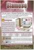
Advert (GB)
1996-12
Advert (GB)
1997-03
Manufacturer TrueVision, USA | Date 1990 | Amiga A2000, A3000, A4000 | Interface ISA |
- framebuffer
- while strictly PC boards, some Amiga applications directly support them as framebuffers through a BridgeBoard with Janus software
- Caligari Broadcast has native support for the Targa boards (including saving in Targa format, automatic transferring through the BridgeBoard and loading the image into the Targa framebuffer)
- Sculpt renders directly through the Sculpt-Direct and Targa-Direct (TGALink) modules of Active Circuits' ImageLink software
- the various Targa, Targa+ and ATVista boards can do much more than displaying 24 bit images in their framebuffer, but those features (capture, live overlay, keying, etc.) are not utilized by Amiga applications
Manufacturer PreVue Technologies, USA | Amiga A2000, A3000, A4000 | Interface ISA |
- sync generator
- designed to advance the sync reference signal for the Video Toaster so that the Toaster Program output signal will be in time with the sync reference signal
- the sync reference can be either a standard Black Burst reference signal or any other stable test signal
- separate subcarrier and horizontal adjustments are provided to establish SC/H phasing
- a reference signal must be supplied to the Toast Timer - it is not designed to be used as a stand alone Black Burst generator and will not provide a proper signal without a reference input
- includes a jumper that allows for extended range for use with other Video Toaster accessories such as Y/C interface boards
- when the Toast Timer is used in conjunction with 1 or 2 BreadBoards feeding another downstream switcher, it is recommended that a Program output feed from one of the BreadBoards be connected as the Video Toaster input to the downstream switcher

front side

front side
Manufacturer Y/C Plus Inc., USA | Date 1996 | Amiga A2000, A3000, A4000 | Interface ISA |
- Video Toaster calibrator
- helps eliminating "Toaster Not Responding", "Toaster Will Not Genlock" or "Toaster Will Not Auto Hue" error messages
- calibrates Video Toaster's onboard crystal oscillator
- connects to the Video Toaster JP6 connector by a ribbon cable
- checks the computer's power supply - displays proper +12V, -12V, +5V, -5V voltages with easy to view LED's
- the card is designed to be installed, perform the necessary procedures and then be removed, so a permanent card slot is not required

front side